Page 2314 of 4323
I28487
Multi±display
Controller Sub±assy D23
Disc Player Controller
ACC
GND12
11
15+BACC3
GND4 +BR22
R22
R22 LGLG
LG 19
20
16 DI±2112
± DIAGNOSTICSREAR SEAT ENTERTAINMANT SYSTEM
2306 Author�: Date�:
2005 SEQUOIA (RM1146U)
Power source circuit (Disc player controller)
CIRCUIT DESCRIPTION
This circuit provides power to the disc player controller. The power is sent from the battery to the disc player
controller through the multi±display controller sub±assy.
WIRING DIAGRAM
DIDB6±01
Page 2315 of 4323

I28664
+BACC
GND
Disc Player Controller:
D23
± DIAGNOSTICSREAR SEAT ENTERTAINMANT SYSTEM
DI±2113
2307 Author�: Date�:
2005 SEQUOIA (RM1146U)
INSPECTION PROCEDURE
1 Inspect disc player controller (+B, ACC, GND).
PREPARATION:
Disconnect the D23 connector.
CHECK:
Measure the resistance according to the value(s) in the table
below.
OK:
Symbol (Tester connection)ConditionSpecified condition
GND (D23±16) ± Body groundAlwaysBelow 1 W
CHECK:
Measure the voltage according to the value(s) in the table be-
low.
OK:
Symbol (Tester connection)ConditionSpecified condition
+B (D23±20) ± GND (D23±16)Always10 to 14 V
ACC (D23±19) ± GND (D23±16)Ignition SW ACC10 to 14 V
NG Go to step 3.
OK
2 Check problem symptoms table.
CHECK:
Check the problem symptoms table.
RESULT:
All possible suspected areas have been inspectedGo to step A
Possible suspected areas still existGo to step B
B Proceed to next circuit inspection shown in
problem symptoms table or diagnostic trouble
code chart (See page DI±2087 or DI±2103).
A
Replace disc player controller.
Page 2316 of 4323
I28330
Disc Player Controller:
Multi±display Controller Sub±assy:
+BACC3 GND4D23
R22
+BACC
GND
DI±2114
± DIAGNOSTICSREAR SEAT ENTERTAINMANT SYSTEM
2308 Author�: Date�:
2005 SEQUOIA (RM1146U)
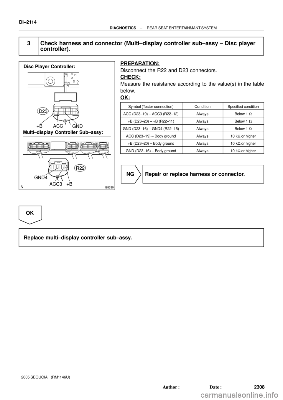
3 Check harness and connector (Multi±display controller sub±assy ± Disc player
controller).
PREPARATION:
Disconnect the R22 and D23 connectors.
CHECK:
Measure the resistance according to the value(s) in the table
below.
OK:
Symbol (Tester connection)ConditionSpecified condition
ACC (D23±19) ± ACC3 (R22±12)AlwaysBelow 1 W
+B (D23±20) ± +B (R22±11)AlwaysBelow 1 W
GND (D23±16) ± GND4 (R22±15)AlwaysBelow 1 W
ACC (D23±19) ± Body groundAlways10 kW or higher
+B (D23±20) ± Body groundAlways10 kW or higher
GND (D23±16) ± Body groundAlways10 kW or higher
NG Repair or replace harness or connector.
OK
Replace multi±display controller sub±assy.
Page 2319 of 4323
I28666
Multi±display
Controller Sub±assy
NTS2
SGN2
SG9 R228
R229
R2210 BR
BR NTSC
S.GND
SLD3
2
1
(Shielded) D23
Disc Player Controller
± DIAGNOSTICSREAR SEAT ENTERTAINMANT SYSTEM
DI±2117
2311 Author�: Date�:
2005 SEQUOIA (RM1146U)
Display signal circuit (Multi±display controller sub±assy ± Disc
player controller)
CIRCUIT DESCRIPTION
This is the display signal circuit from the disc player controller to the multi±display controller sub±assy.
WIRING DIAGRAM
DIDB8±01
Page 2320 of 4323
I28326
Disc Player Controller:
Multi±display Controller Sub±assy:SLD S.GND
NTSC
NTS2
SGN2 SG9
D23
R22
DI±2118
± DIAGNOSTICSREAR SEAT ENTERTAINMANT SYSTEM
2312 Author�: Date�:
2005 SEQUOIA (RM1146U)
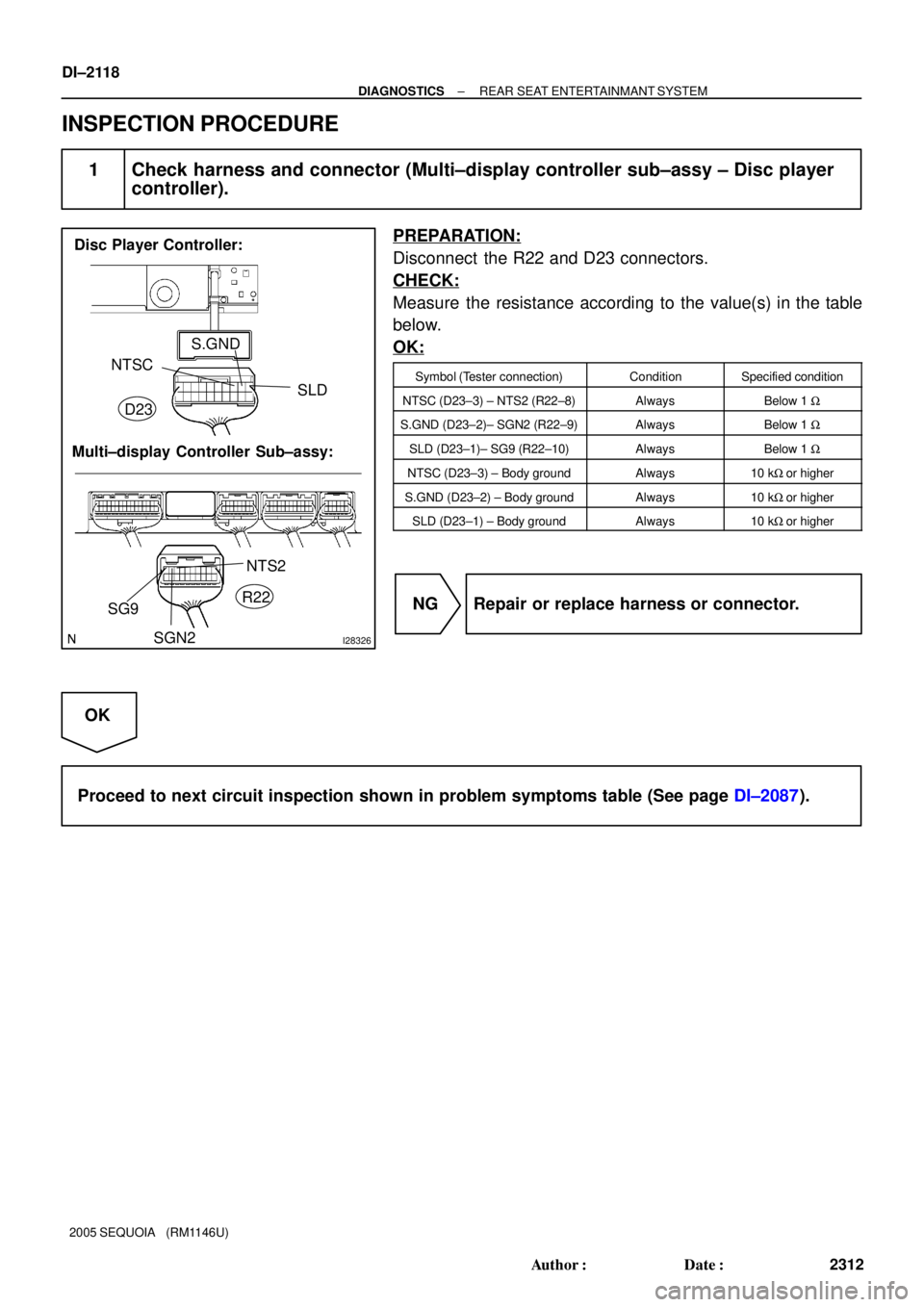
INSPECTION PROCEDURE
1 Check harness and connector (Multi±display controller sub±assy ± Disc player
controller).
PREPARATION:
Disconnect the R22 and D23 connectors.
CHECK:
Measure the resistance according to the value(s) in the table
below.
OK:
Symbol (Tester connection)ConditionSpecified condition
NTSC (D23±3) ± NTS2 (R22±8)AlwaysBelow 1 W
S.GND (D23±2)± SGN2 (R22±9)AlwaysBelow 1 W
SLD (D23±1)± SG9 (R22±10)AlwaysBelow 1 W
NTSC (D23±3) ± Body groundAlways10 kW or higher
S.GND (D23±2) ± Body groundAlways10 kW or higher
SLD (D23±1) ± Body groundAlways10 kW or higher
NG Repair or replace harness or connector.
OK
Proceed to next circuit inspection shown in problem symptoms table (See page DI±2087).
Page 2339 of 4323
I28669
AR+
AR±
AL+
AL±
SG4
(Shielded)R22 6
7
8
9
55
4
3
2
6 R22 R22 R22 R22 R+
R±
L+
L±
SLDW
W
W
W D23
Disc Player ControllerMulti±display
Controller Sub±assy
± DIAGNOSTICSREAR SEAT ENTERTAINMANT SYSTEM
DI±2137
2331 Author�: Date�:
2005 SEQUOIA (RM1146U)
Sound signal circuit (Multi±display controller sub±assy ± Disc
player controller)
CIRCUIT DESCRIPTION
This is the sound signal circuit from the disc player controller to the multi±display controller sub±assy.
WIRING DIAGRAM
DIDBI±01
Page 2340 of 4323
I28330
Disc Player Controller:
Multi±display Controller Sub±assy:
R+L+R± L±
SLD
AL+AR+
AR±SG4AL± D23
R22
DI±2138
± DIAGNOSTICSREAR SEAT ENTERTAINMANT SYSTEM
2332 Author�: Date�:
2005 SEQUOIA (RM1146U)
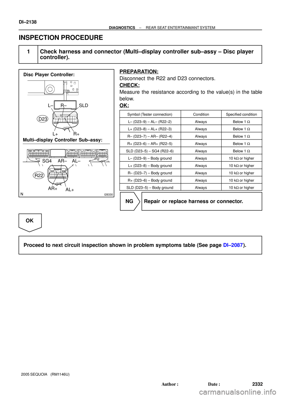
INSPECTION PROCEDURE
1 Check harness and connector (Multi±display controller sub±assy ± Disc player
controller).
PREPARATION:
Disconnect the R22 and D23 connectors.
CHECK:
Measure the resistance according to the value(s) in the table
below.
OK:
Symbol (Tester connection)ConditionSpecified condition
L± (D23±9) ± AL± (R22±2)AlwaysBelow 1 W
L+ (D23±8) ± AL+ (R22±3)AlwaysBelow 1 W
R± (D23±7) ± AR± (R22±4)AlwaysBelow 1 W
R+ (D23±6) ± AR+ (R22±5)AlwaysBelow 1 W
SLD (D23±5) ± SG4 (R22±6)AlwaysBelow 1 W
L± (D23±9) ± Body groundAlways10 kW or higher
L+ (D23±8) ± Body groundAlways10 kW or higher
R± (D23±7) ± Body groundAlways10 kW or higher
R+ (D23±6) ± Body groundAlways10 kW or higher
SLD (D23±5) ± Body groundAlways10 kW or higher
NG Repair or replace harness or connector.
OK
Proceed to next circuit inspection shown in problem symptoms table (See page DI±2087).
Page 2341 of 4323

I28592
Multi±display
Controller Sub±assy R25
Television Display Assy
IF49
LG5
TX2+ ID217
R21
LG LG
IF410
LG4
TX2± ID218
R21
LG LG TX+
TX±
LG31
TX+
IF314
R23
L
LG30
TX± IF315
R23
LG TX+ (*1)9
10
9
10 � R27 (*1)
Radio and Navigation Assy
� R19 (*2)
Radio Receiver Assy
D23
Disc Player Controller
13
TX3± R22
LG
14
TX3+ R22 TX±
TX+18
17
LG
*1: w/ Navigation System
*2: w/o Navigation SystemTX1+ (*2)
TX± (*1)
TX1± (*2)
± DIAGNOSTICSREAR SEAT ENTERTAINMANT SYSTEM
DI±2139
2333 Author�: Date�:
2005 SEQUOIA (RM1146U)
AVC±LAN circuit
CIRCUIT DESCRIPTION
Each unit of this system connected to the AVC±LAN (communication bus) transfers the signal of each switch
by communication.
When a short to +B or short to ground occurs in this AVC± LAN, this system will not function normally as
communication is discontinued.
This system has 2 kinds of AVC±LAN: main AVC±LAN and sub AVC±LAN.
w/ navigation system:
In the main AVC±LAN, the radio and navigation assy becomes the communication master and has enough
resistance necessary for communication.
w/o navigation system:
In the main AVC±LAN, the radio receiver assy becomes the communication master and has enough resis-
tance necessary for communication.
In the sub AVC±LAN, the multi±display controller sub±assy becomes the communication master and has
enough resistance necessary for communication.
WIRING DIAGRAM
DIDBJ±01