Page 3032 of 4323

SA23J±05
SA±28
± SUSPENSION AND AXLEFRONT AXLE HUB
3024 Author�: Date�:
2005 SEQUOIA (RM1146U)
INSTALLATION
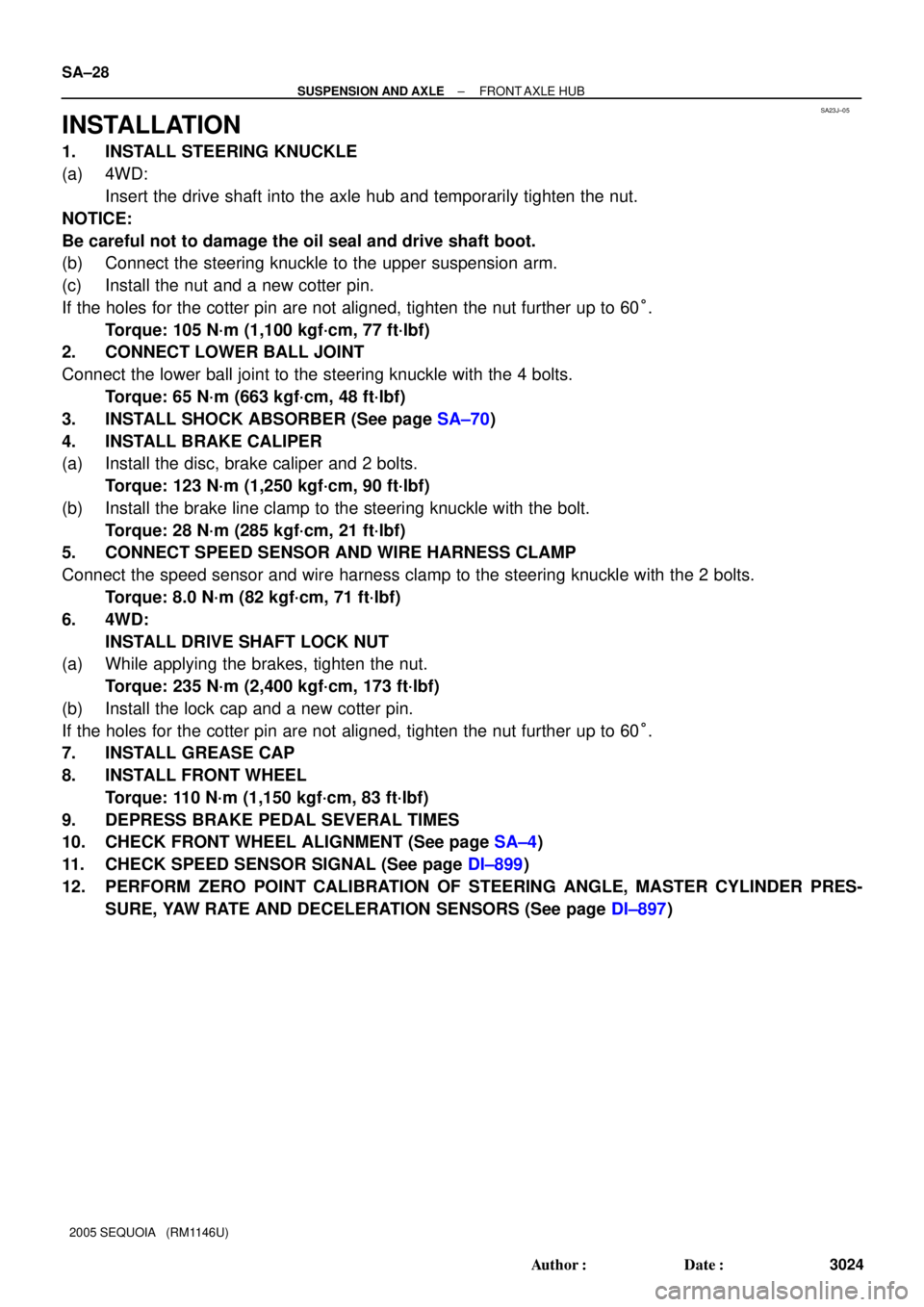
1. INSTALL STEERING KNUCKLE
(a) 4WD:
Insert the drive shaft into the axle hub and temporarily tighten the nut.
NOTICE:
Be careful not to damage the oil seal and drive shaft boot.
(b) Connect the steering knuckle to the upper suspension arm.
(c) Install the nut and a new cotter pin.
If the holes for the cotter pin are not aligned, tighten the nut further up to 60°.
Torque: 105 N´m (1,100 kgf´cm, 77 ft´lbf)
2. CONNECT LOWER BALL JOINT
Connect the lower ball joint to the steering knuckle with the 4 bolts.
Torque: 65 N´m (663 kgf´cm, 48 ft´lbf)
3. INSTALL SHOCK ABSORBER (See page SA±70)
4. INSTALL BRAKE CALIPER
(a) Install the disc, brake caliper and 2 bolts.
Torque: 123 N´m (1,250 kgf´cm, 90 ft´lbf)
(b) Install the brake line clamp to the steering knuckle with the bolt.
Torque: 28 N´m (285 kgf´cm, 21 ft´lbf)
5. CONNECT SPEED SENSOR AND WIRE HARNESS CLAMP
Connect the speed sensor and wire harness clamp to the steering knuckle with the 2 bolts.
Torque: 8.0 N´m (82 kgf´cm, 71 ft´lbf)
6. 4WD:
INSTALL DRIVE SHAFT LOCK NUT
(a) While applying the brakes, tighten the nut.
Torque: 235 N´m (2,400 kgf´cm, 173 ft´lbf)
(b) Install the lock cap and a new cotter pin.
If the holes for the cotter pin are not aligned, tighten the nut further up to 60°.
7. INSTALL GREASE CAP
8. INSTALL FRONT WHEEL
Torque: 110 N´m (1,150 kgf´cm, 83 ft´lbf)
9. DEPRESS BRAKE PEDAL SEVERAL TIMES
10. CHECK FRONT WHEEL ALIGNMENT (See page SA±4)
11. CHECK SPEED SENSOR SIGNAL (See page DI±899)
12. PERFORM ZERO POINT CALIBRATION OF STEERING ANGLE, MASTER CYLINDER PRES-
SURE, YAW RATE AND DECELERATION SENSORS (See page DI±897)
Page 3078 of 4323

SA187±06
SA±74
± SUSPENSION AND AXLEFRONT UPPER SUSPENSION ARM
3070 Author�: Date�:
2005 SEQUOIA (RM1146U)
INSTALLATION
1. INSTALL UPPER SUSPENSION ARM
Install the upper suspension arm with the 2 washers, bolt and nut.
Torque: 98 N´m (1,000 kgf´cm, 72 ft´lbf)
HINT:
After stabilizing the suspension, torque the nut.
2. INSTALL BRAKE AND FUEL LINE CLAMP
Torque: 5.5 N´m (56 kgf´cm, 49 in.´lbf)
3. INSTALL FENDER APRON SEAL REAR
4. CONNECT UPPER BALL JOINT
(a) Connect the upper ball joint to the upper suspension arm.
(b) Install the nut and a new cotter pin.
If the holes for the cotter pin are not aligned, tighten the nut further up to 60°.
Torque: 105 N´m (1,100 kgf´cm, 77 ft´lbf)
5. CONNECT SPEED SENSOR WIRE HARNESS CLAMPS
Torque: 8.0 N´m (82 kgf´cm, 71 in.´lbf)
6. INSTALL SHOCK ABSORBER WITH COIL SPRING (See page SA±70)
7. CHECK FRONT WHEEL ALIGNMENT (See page SA±4)
8. PERFORM ZERO POINT CALIBRATION OF STEERING ANGLE, MASTER CYLINDER PRES-
SURE, YAW RATE AND DECELERATION SENSORS (See page DI±897)
Page 3084 of 4323

SA23Y±05
R13282
MatchmarksMatchmarks
F07278
AC
B SA±80
± SUSPENSION AND AXLEFRONT LOWER SUSPENSION ARM
3076 Author�: Date�:
2005 SEQUOIA (RM1146U)
INSTALLATION
1. INSTALL LOWER SUSPENSION ARM TO CHASSIS
FRAME
Install the lower suspension arm with the 2 cams, bolts and cam
plates while slightly shifting the power steering gear rearward.
Torque: 130 N´m (1,325 kgf´cm, 96 ft´lbf)
NOTICE:
Do not damage the power steering gear tubes.
HINT:
After stabilizing the suspension, align the matchmarks on the
front and rear cam plates and chassis frame, and torque the
bolts.
2. CONNECT LOWER BALL JOINT TO LOWER SUSPEN-
SION ARM
Connect the lower ball joint and install the nut and a new cotter
pin.
Torque: 159 N´m (1,621 kgf´cm, 117 ft´lbf)
If the holes for the cotter pin are not aligned, tighten the nut fur-
ther up to 60°.
3. CONNECT SHOCK ABSORBER TO LOWER SUSPEN-
SION ARM
Torque: 135 N´m (1,400 kgf´cm, 100 ft´lbf)
4. CONNECT STABILIZER BAR LINK TO LOWER SUS-
PENSION ARM
Torque: 69 N´m (700 kgf´cm, 51 ft´lbf)
HINT:
If the ball joint turns together with the nut, use a hexagon (6 mm)
wrench to hold the stud.
5. INSTALL POWER STEERING GEAR
Torque:
A bolt: 165 N´m (1,700 kgf´cm, 122 ft´lbf)
B nut: 130 N´m (1,350 kgf´cm, 96 ft´lbf)
C bolt and nut: 165 N´m (1,700 kgf´cm, 122 ft´lbf)
6. CONNECT RH AND LH TIE ROD ENDS
Connect the RH and LH tie rod ends to the lower ball joints with
the nuts and new cotter pins.
Torque: 91 N´m (930 kgf´cm, 67 ft´lbf)
If the holes for the cotter pin are not aligned, tighten the nut fur-
ther up to 60°.
7. INSTALL RH AND LH FRONT WHEELS
Torque: 110 N´m (1,150 kgf´cm, 83 ft´lbf)
8. CHECK FRONT WHEEL ALIGNMENT (See page
SA±4)
9. PERFORM ZERO POINT CALIBRATION OF STEER-
ING ANGLE, MASTER CYLINDER PRESSURE, YAW
RATE AND DECELERATION SENSORS (See page
DI±897)
Page 3229 of 4323
BR1NL±04
BR±54
± BRAKEABS & VSC ACTUATOR
3221 Author�: Date�:
2005 SEQUOIA (RM1146U)
INSTALLATION
Installation is in the reverse order of removal (See page BR±51).
HINT:
�After installation, fill the brake reservoir with brake fluid and bleed brake system (See page BR±4).
�Check for leaks.
NOTICE:
In case of replacing the skid control ECU, perform the zero point calibration of the steering angle,
master cylinder pressure, yawrate and deceleration sensors (See page DI±897).
Page 3948 of 4323

05_SEQUOIA_U (L/O 0408)
89
2005 SEQUOIA from Aug. '04 Prod. (OM34424U)
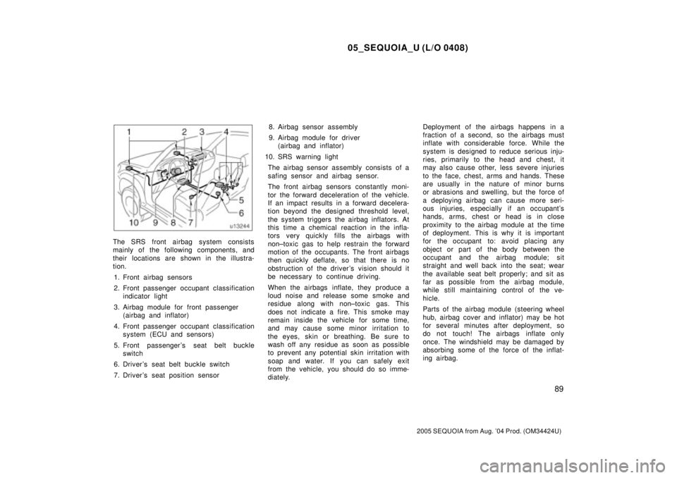
The SRS front airbag system consists
mainly of the following components, and
their locations are shown in the illustra-
tion.
1. Front airbag sensors
2. Front passenger occupant classification
indicator light
3. Airbag module for front passenger
(airbag and inflator)
4. Front passenger occupant classification
system (ECU and sensors)
5. Front passenger 's seat belt buckle
switch
6. Driver 's seat belt buckle switch
7. Driver 's seat position sensor8. Airbag sensor assembly
9. Airbag module for driver
(airbag and inflator)
10. SRS warning light
The airbag sensor assembly consists of a
safing sensor and airbag sensor.
The front airbag sensors constantly moni-
tor the forward deceleration of the vehicle.
If an impact results in a forward decelera-
tion beyond the designed threshold level,
the system triggers the airbag inflators. At
this time a chemical reaction in the infla-
tors very quickly fills the airbags with
non±toxic gas to help restrain the forward
motion of the occupants. The front airbags
then quickly deflate, so that there is no
obstruction of the driver 's vision should it
be necessary to continue driving.
When the airbags inflate, they produce a
loud noise and release some smoke and
residue along with non±toxic gas. This
does not indicate a fire. This smoke may
remain inside the vehicle for some time,
and may cause some minor irritation to
the eyes, skin or breathing. Be sure to
wash off any residue as soon as possible
to prevent any potential skin irritation with
soap and water. If you can safely exit
from the vehicle, you should do so imme-
diately.Deployment of the airbags happens in a
fraction of a second, so the airbags must
inflate with considerable force. While the
system is designed to reduce serious inju-
ries, primarily to the head and chest, it
may also cause other, less severe injuries
to the face, chest, arms and hands. These
are usually in the nature of minor burns
or abrasions and swelling, but the force of
a deploying airbag can cause more seri-
ous injuries, especially if an occupant's
hands, arms, chest or head is in close
proximity to the airbag module at the time
of deployment. This is why it is important
for the occupant to: avoid placing any
object or part of the body between the
occupant and the airbag module; sit
straight and well back into the seat; wear
the available seat belt properly; and sit as
far as possible from the airbag module,
while still maintaining control of the ve-
hicle.
Parts of the airbag module (steering wheel
hub, airbag cover and inflator) may be hot
for several minutes after deployment, so
do not touch! The airbags inflate only
once. The windshield may be damaged by
absorbing some of the force of the inflat-
ing airbag.
Page 4202 of 4323

05_SEQUOIA_U (L/O 0408)
343
2005 SEQUOIA from Aug. '04 Prod. (OM34424U)
�Driving with tire chains installed.
�Driving over the steps such as the
joints on the road.
�Driving on roads where the road
surface is pitted or has other differ-
ences in surface height.
Install all 4 tires of specified size at
appropriate pressure: The anti±lock
brake system detects vehicle speeds
using the speed sensors for respec-
tive wheels' turning speeds. The use
of tires other than specified may fail
to detect the accurate turning speed
resulting in a longer stopping dis-
tance.
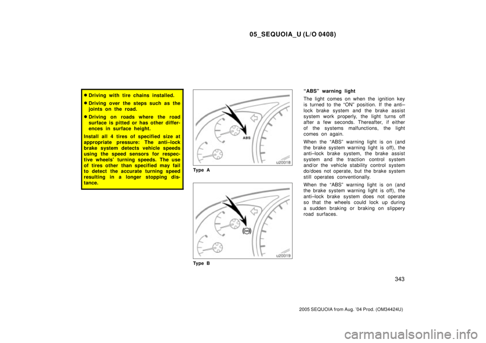
Ty p e A
Ty p e B
ªABSº warning light
The light comes on when the ignition key
is turned to the ªONº position. If the anti±
lock brake system and the brake assist
system work properly, the light turns off
after a few seconds. Thereafter, if either
of the systems malfunctions, the light
comes on again.
When the ªABSº warning light is on (and
the brake system warning light is off), the
anti±lock brake system, the brake assist
system and the traction control system
and/or the vehicle stability control system
do/does not operate, but the brake system
still operates conventionally.
When the ªABSº warning light is on (and
the brake system warning light is off), the
anti±lock brake system does not operate
so that the wheels could lock up during
a sudden braking or braking on slippery
road surfaces.
Page:
< prev 1-8 9-16 17-24