Page 3321 of 4323

RS0BC±08
RS±30
± SUPPLEMENTAL RESTRAINT SYSTEMSTEERING WHEEL PAD AND SPIRAL CABLE
3313 Author�: Date�:
2005 SEQUOIA (RM1146U)
REPLACEMENT
REPLACEMENT REQUIREMENTS
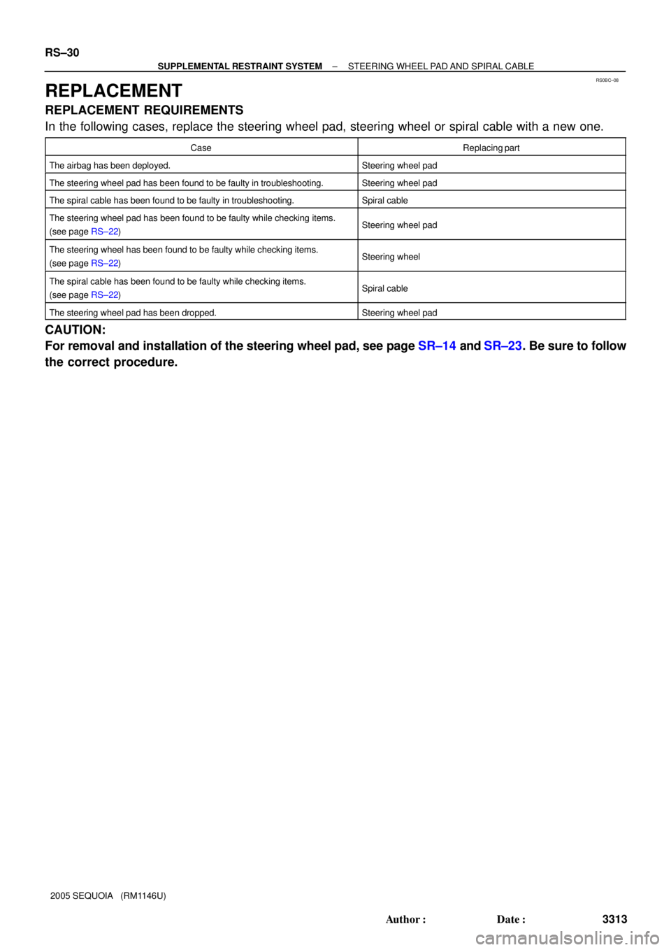
In the following cases, replace the steering wheel pad, steering wheel or spiral cable with a new one.
CaseReplacing part
The airbag has been deployed.Steering wheel pad
The steering wheel pad has been found to be faulty in troubleshooting.Steering wheel pad
The spiral cable has been found to be faulty in troubleshooting.Spiral cable
The steering wheel pad has been found to be faulty while checking items.
(see page RS±22)Steering wheel pad
The steering wheel has been found to be faulty while checking items.
(see page RS±22)Steering wheel
The spiral cable has been found to be faulty while checking items.
(see page RS±22)Spiral cable
The steering wheel pad has been dropped.Steering wheel pad
CAUTION:
For removal and installation of the steering wheel pad, see page SR±14 and SR±23. Be sure to follow
the correct procedure.
Page 3322 of 4323
RS0BD±11
± SUPPLEMENTAL RESTRAINT SYSTEMSTEERING WHEEL PAD AND SPIRAL CABLE
RS±31
3314 Author�: Date�:
2005 SEQUOIA (RM1146U)
INSTALLATION
CAUTION:
�If the steering wheel pad has been dropped, or there are cracks, dents or other defects in the
case or connector, replace the steering wheel pad with a new one.
�When installing the steering wheel pad, take care it is not pinched between other parts.
�Never use airbag parts from another vehicle. When replacing parts, replace them with new
ones.
1. INSTALL SPIRAL CABLE (SEE PAGE SR±23)
2. INSTALL STEERING COLUMN COVER LOWER (SEE PAGE SR±23)
3. INSTALL STEERING WHEEL (SEE PAGE SR±23)
4. INSTALL STEERING WHEEL PAD (SEE PAGE SR±23)
5. CONNECT CABLE TO NEGATIVE BATTERY TERMINAL
6. PERFORM INITIALIZATION (SEE PAGE SR±23)
Some system need initialization when disconnecting the cable from the negative battery terminal.
7. INSPECT SRS WARNING LIGHT (SEE PAGE DI±1137)
Page 3331 of 4323

H24665
Tires
(2 or more)
Tires
(2 or more)
H23917
H24672
Battery
SSTFront Passenger
Airbag Assembly
10 m (33 ft) or more
RS±40
± SUPPLEMENTAL RESTRAINT SYSTEMFRONT PASSENGER AIRBAG ASSEMBLY
3323 Author�: Date�:
2005 SEQUOIA (RM1146U)
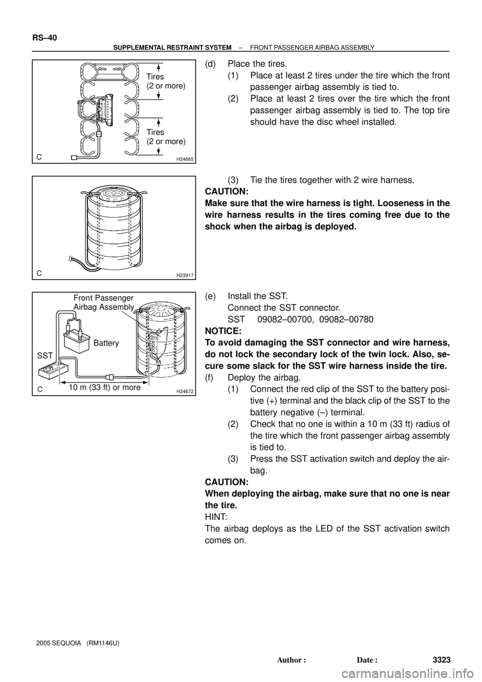
(d) Place the tires.
(1) Place at least 2 tires under the tire which the front
passenger airbag assembly is tied to.
(2) Place at least 2 tires over the tire which the front
passenger airbag assembly is tied to. The top tire
should have the disc wheel installed.
(3) Tie the tires together with 2 wire harness.
CAUTION:
Make sure that the wire harness is tight. Looseness in the
wire harness results in the tires coming free due to the
shock when the airbag is deployed.
(e) Install the SST.
Connect the SST connector.
SST 09082±00700, 09082±00780
NOTICE:
To avoid damaging the SST connector and wire harness,
do not lock the secondary lock of the twin lock. Also, se-
cure some slack for the SST wire harness inside the tire.
(f) Deploy the airbag.
(1) Connect the red clip of the SST to the battery posi-
tive (+) terminal and the black clip of the SST to the
battery negative (±) terminal.
(2) Check that no one is within a 10 m (33 ft) radius of
the tire which the front passenger airbag assembly
is tied to.
(3) Press the SST activation switch and deploy the air-
bag.
CAUTION:
When deploying the airbag, make sure that no one is near
the tire.
HINT:
The airbag deploys as the LED of the SST activation switch
comes on.
Page 3345 of 4323

H17497
H24673
Width
Inner
Diameter
H24674
SST
H24675
Tires
(2 or more)
Tires
(2 or more)
RS±54
± SUPPLEMENTAL RESTRAINT SYSTEMSIDE AIRBAG ASSEMBLY (Power Adjuster Type)
3337 Author�: Date�:
2005 SEQUOIA (RM1146U)
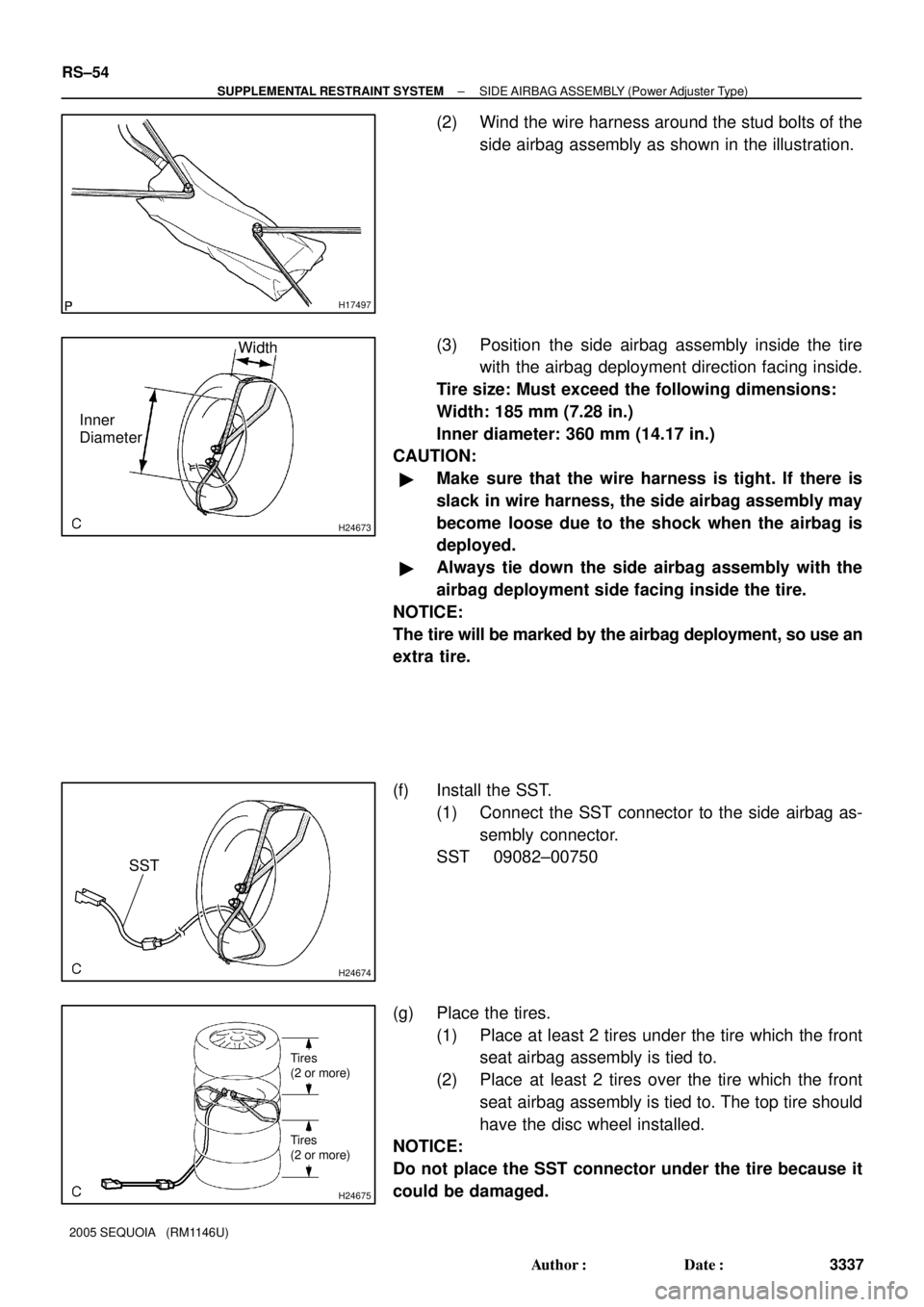
(2) Wind the wire harness around the stud bolts of the
side airbag assembly as shown in the illustration.
(3) Position the side airbag assembly inside the tire
with the airbag deployment direction facing inside.
Tire size: Must exceed the following dimensions:
Width: 185 mm (7.28 in.)
Inner diameter: 360 mm (14.17 in.)
CAUTION:
�Make sure that the wire harness is tight. If there is
slack in wire harness, the side airbag assembly may
become loose due to the shock when the airbag is
deployed.
�Always tie down the side airbag assembly with the
airbag deployment side facing inside the tire.
NOTICE:
The tire will be marked by the airbag deployment, so use an
extra tire.
(f) Install the SST.
(1) Connect the SST connector to the side airbag as-
sembly connector.
SST 09082±00750
(g) Place the tires.
(1) Place at least 2 tires under the tire which the front
seat airbag assembly is tied to.
(2) Place at least 2 tires over the tire which the front
seat airbag assembly is tied to. The top tire should
have the disc wheel installed.
NOTICE:
Do not place the SST connector under the tire because it
could be damaged.
Page 3368 of 4323

H23928
SST
H23929
Tires
(5 or more)
H23917
H2467110 m (33 ft) or more SST
Battery Curtain Shied Airbag Assembly
± SUPPLEMENTAL RESTRAINT SYSTEMCURTAIN SHIELD AIRBAG ASSEMBLY
RS±77
3360 Author�: Date�:
2005 SEQUOIA (RM1146U)
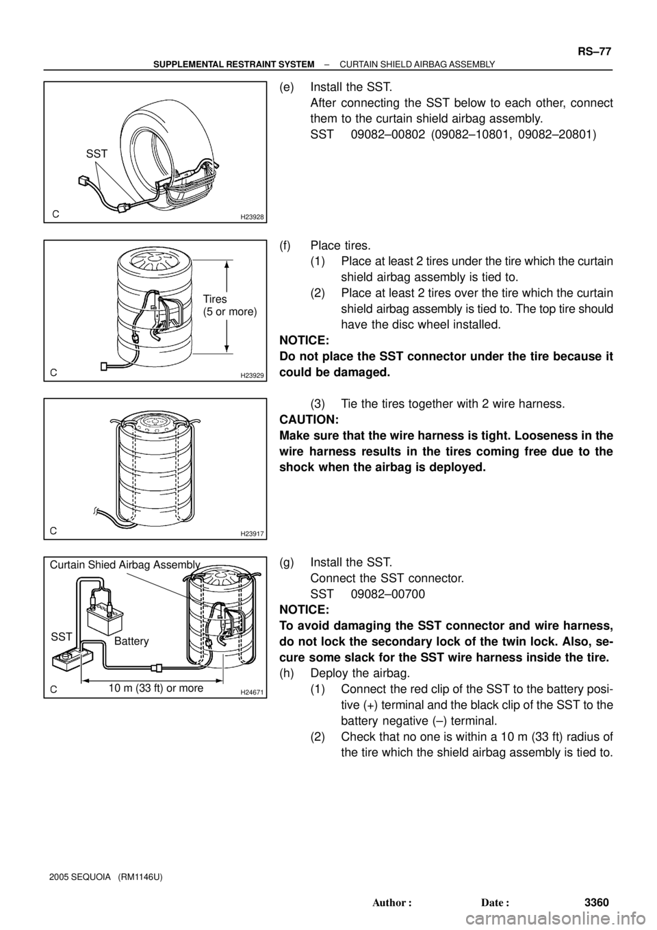
(e) Install the SST.
After connecting the SST below to each other, connect
them to the curtain shield airbag assembly.
SST 09082±00802 (09082±10801, 09082±20801)
(f) Place tires.
(1) Place at least 2 tires under the tire which the curtain
shield airbag assembly is tied to.
(2) Place at least 2 tires over the tire which the curtain
shield airbag assembly is tied to. The top tire should
have the disc wheel installed.
NOTICE:
Do not place the SST connector under the tire because it
could be damaged.
(3) Tie the tires together with 2 wire harness.
CAUTION:
Make sure that the wire harness is tight. Looseness in the
wire harness results in the tires coming free due to the
shock when the airbag is deployed.
(g) Install the SST.
Connect the SST connector.
SST 09082±00700
NOTICE:
To avoid damaging the SST connector and wire harness,
do not lock the secondary lock of the twin lock. Also, se-
cure some slack for the SST wire harness inside the tire.
(h) Deploy the airbag.
(1) Connect the red clip of the SST to the battery posi-
tive (+) terminal and the black clip of the SST to the
battery negative (±) terminal.
(2) Check that no one is within a 10 m (33 ft) radius of
the tire which the shield airbag assembly is tied to.
Page 3410 of 4323
RS0BU±10
H23906
Front Airbag Sensor (LH)Front Airbag
Sensor (RH)Front Passenger
Airbag Assembly (RH)
Seat Belt
Pretensioner (RH)
Airbag Sensor Assembly Seat Belt Pretensioner (LH) Spiral CableCurtain Shield
Airbag Assembly (RH)
Side Airbag
Assembly (RH) (*1)
Side Airbag Sensor
Assembly (RH) (*1)
Side Airbag Assembly (LH) (*1) Side Airbag Sensor
Assembly (LH) (*1)
Curtain Shield Airbag
Assembly (LH) (*1)
Combination Meter
(Warning Light)
Steering Wheel Pad
(With Airbag)
Curtain Shield Airbag
Sensor Assembly (LH) (*1)
Curtain Shield Airbag
Sensor Assembly
(RH) (*1)RSCA OFF
Switch (*1)
Occupant Classification
ECU (*1)
(*1) w/ Side Airbag and Curtain Shield Airbag
± SUPPLEMENTAL RESTRAINT SYSTEMWIRE HARNESS AND CONNECTOR
RS±119
3402 Author�: Date�:
2005 SEQUOIA (RM1146U)
WIRE HARNESS AND CONNECTOR
LOCATION
Page 3557 of 4323

BE0FZ±25
I24377
I24378
I04197
± BODY ELECTRICALHORN SYSTEM
BE±145
3549 Author�: Date�:
2005 SEQUOIA (RM1146U)
INSPECTION
1. INSPECT HORN SWITCH
(a) Disconnect the negative (±) terminal from the battery.
(b) Remove the left and right covers from the steering wheel.
(c) Using a torx socket wrench, loosen the 2 bolts.
(d) Pull up the horn pad and place it on the steering column,
as shown.
HINT:
Do not disconnect the connector from the horn pad.
(e) Disconnect the connector from the slip ring.
(f) Check that no continuity exists between terminal 6 of the
connector and body ground.
(g) Check that continuity exists between terminal 6 of the
connector and body ground when the horn contact plate
is pressed against the steering spoke assembly.
If continuity is not as specified, repair or replace the steering
wheel or wire harness as necessary.
(h) Install the horn pad in place and using a torx socket
wrench, torque the 2 bolts.
Torque:
7.1 N´m (72 kgf´cm, 62 in.´lbf)
(i) Install the left and right covers.
(j) Connect the negative (±) terminal to the battery.
2. INSPECT HORN OPERATION
Connect the positive (+) lead from the battery to the terminal
and negative (±) lead to the horn body and check that the horn
blows.
If operation is not as specified, replace the horn.
3. INSPECT HORN SWITCH CIRCUIT
(See page DI±1764)
Page 3567 of 4323
BO45I±02
H24349N´m (kgf´cm, ft´lbf)
: Specified torque Rear Bumper
Reinforcement
95 (970, 70)
7.0 (71, 62 in.´lbf)
Quarter Wheel Opening Moulding
Rear Bumper Cover Rear Bumper Side Support
Reflex Reflector Rear Bumper Protection Rear Bumper SealBack Step Reinforcement Rear Mud Guard
Rear Bumper Side Support
19 (195, 14)
19 (195, 14)
19 (195, 14)
19 (195, 14)
7.0 (71, 62 in.´lbf)
5.0 (50, 43 in.´lbf)
95 (970, 70)
5.0 (50, 43 in.´lbf)
7.0 (71, 62 in.´lbf)
7.0 (71, 62 in.´lbf)
Side Support
Rear Bumper Extension
7.0 (71, 62 in.´lbf)
7.0 (71, 62 in.´lbf)
95 (970, 70)
95 (970, 70)
x4x4x4
x4
Rear Mud Guard
BO±6
± BODYREAR BUMPER
3559 Author�: Date�:
2005 SEQUOIA (RM1146U)
REAR BUMPER
COMPONENTS