Page 3768 of 4323

AC3H3±02
I11129
I11197
Water Hose
Heater Radiator
PipeUpper
LH
RH
45 ± 10°
Lower
Hose Clip
Second RidgeLH
RH
I11130
± AIR CONDITIONINGHEATER UNIT
AC±33
3760 Author�: Date�:
2005 SEQUOIA (RM1146U)
REMOVAL
1. REMOVE COOLING UNIT (See page AC±26)
2. DRAIN ENGINE COOLANT FROM RADIATOR
HINT:
It is not necessary to drain out all the coolant.
3. DISCONNECT WATER VALVE CONTROL CABLE
FROM WATER VALVE (See page AC±79)
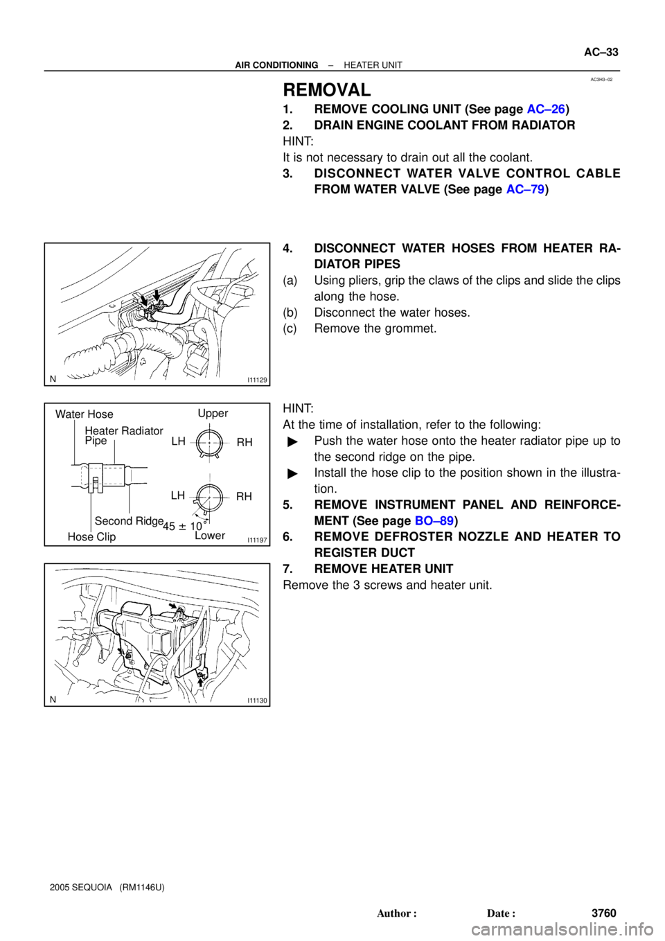
4. DISCONNECT WATER HOSES FROM HEATER RA-
DIATOR PIPES
(a) Using pliers, grip the claws of the clips and slide the clips
along the hose.
(b) Disconnect the water hoses.
(c) Remove the grommet.
HINT:
At the time of installation, refer to the following:
�Push the water hose onto the heater radiator pipe up to
the second ridge on the pipe.
�Install the hose clip to the position shown in the illustra-
tion.
5. REMOVE INSTRUMENT PANEL AND REINFORCE-
MENT (See page BO±89)
6. REMOVE DEFROSTER NOZZLE AND HEATER TO
REGISTER DUCT
7. REMOVE HEATER UNIT
Remove the 3 screws and heater unit.
Page 3769 of 4323
I21798
AC3H4±02
AC±34
± AIR CONDITIONINGHEATER UNIT
3761 Author�: Date�:
2005 SEQUOIA (RM1146U)
DISASSEMBLY
1. REMOVE HEATER RADIATOR
(a) Remove the 3 screws and 3 clamps.
(b) Pull out the heater radiator.
(c) Remove the 2 screws and 2 clips, then disconnect the
heater radiator pipes.
2. REMOVE AIR VENT DUCT
Remove the 3 screws and duct.
3. REMOVE AIR OUTLET SERVOMOTOR
Remove the 3 screws and servomotor.
4. REMOVE AIR MIX SERVOMOTOR
Remove the 3 screws and servomotor.
5. REMOVE ASPIRATOR HOSE
Page 3770 of 4323
AC3H5±02
I22635
FACE
B/L
FOOT
F/D
DEF
2
1 8
7
6
5
4
± AIR CONDITIONINGHEATER UNIT
AC±35
3762 Author�: Date�:
2005 SEQUOIA (RM1146U)
INSPECTION
1. INSPECT FINS FOR BLOCKAGE
If the fins are clogged, clean them with compressed air.
2. INSPECT AIR OUTLET SERVOMOTOR OPERATION
(a) Connect the positive (+) lead from the battery to terminal
2 and the negative (±) lead to terminal 1.
(b) Connect the negative (±) lead from the battery to each ter-
minal and check that the shaft rotates at each position, as
shown in the illustration.
Connected terminalPosition
4DEF
5F/D
6FOOT
7B/L
8FACE
Page 3771 of 4323
AC3H6±01
AC±36
± AIR CONDITIONINGHEATER UNIT
3763 Author�: Date�:
2005 SEQUOIA (RM1146U)
REASSEMBLY
Reassembly is in the reverse order of disassembly (See page AC±34).
Page 3772 of 4323
AC3H7±01
± AIR CONDITIONINGHEATER UNIT
AC±37
3764 Author�: Date�:
2005 SEQUOIA (RM1146U)
INSTALLATION
Installation is in the reverse order of removal (See page AC±33).
Page 3773 of 4323
AC3H8±02
I21376
Rear Cooler
Duct Rear Heater Duct
Plate
Rear A/C Unit
Upper Back Door Garnish
Quarter
Pillar
Garnish RH
Rear Seat
Outer Belt
Rear Window
Side Garnish RH
Water Hose
Wire Harness
Suction Tube
Rear Seat
Outer Belt
Rear Quarter Trim
Panel RHBack Door
Scuff Plate
Rear Door Scuff Plate RH
Liquid Tube
� O±Ring
N´m (kgf´cm, in´lbf):Specified torque� Non±reusable part
5.4 (55, 48)
AC±38
± AIR CONDITIONINGREAR A/C UNIT
3765 Author�: Date�:
2005 SEQUOIA (RM1146U)
REAR A/C UNIT
COMPONENTS
Page 3774 of 4323
I21394
Wire HarnessSliding Door
Air Outlet ServomotorPlate
Water Valve
Hose Clip
Water Hose
Bracket
Packing Heater RadiatorWater Hose
Blower MotorBlower CaseShaftClamp
Bracket
A/C Unite Case RH � O±Ring
Hose Clip
Power Transistor
Evaporator
� O±Ring
Evaporator CoverThermistor
Plate
Tube and Accessory
� O±Ring
Expansion Valve
Clamp
� O±RingLiquid Tube
Bracket
Bracket
N´m (kgf´cm, ft´lbf):Specified torque
� Non±reusable part
InsulatorDrain Hose
A/C Unite Case LH
5.4 (55, 48 in.´lbf)
Packing
22 (235, 16)
13 (135, 10)
± AIR CONDITIONINGREAR A/C UNIT
AC±39
3766 Author�: Date�:
2005 SEQUOIA (RM1146U)
Page 3775 of 4323

AC3H9±02
I21380
I21381
AC±40
± AIR CONDITIONINGREAR A/C UNIT
3767 Author�: Date�:
2005 SEQUOIA (RM1146U)
REMOVAL
1. DISCHARGE REFRIGERANT FROM REFRIGERATION
SYSTEM
HINT:
At the time of installation, refer to the following item:
�Evacuate air from the refrigeration system.
�Charge the system with refrigerant and inspect for leak-
age of refrigerant.
Specified amount:
Dual A/C: 1050 ± 50 g (37.03 ± 1.76 oz.)
2. DRAIN ENGINE COOLANT FROM RADIATOR
HINT:
It is not necessary to drain out all coolant.
3. REMOVE REAR SEAT OUTER BELT FLOOR AN-
CHORS
4. REMOVE BACK DOOR SCUFF PLATE
5. REMOVE REAR DOOR SCUFF PLATE RH
6. REMOVE UPPER BACK DOOR GARNISH
7. REMOVE REAR WINDOW SIDE GARNISH RH
8. REMOVE REAR QUARTER TRIM PANEL RH
9. REMOVE QUARTER PILLAR GARNISH RH
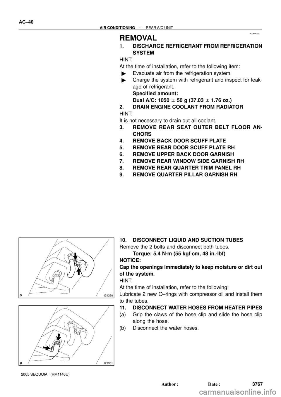
10. DISCONNECT LIQUID AND SUCTION TUBES
Remove the 2 bolts and disconnect both tubes.
Torque: 5.4 N´m (55 kgf´cm, 48 in.´lbf)
NOTICE:
Cap the openings immediately to keep moisture or dirt out
of the system.
HINT:
At the time of installation, refer to the following:
Lubricate 2 new O±rings with compressor oil and install them
to the tubes.
11. DISCONNECT WATER HOSES FROM HEATER PIPES
(a) Grip the claws of the hose clip and slide the hose clip
along the hose.
(b) Disconnect the water hoses.