Page 1108 of 4323
 VSC does not operate
Only when 1. to 9. are all normal and the problem is still
occurring, rep")
DI±906
± DIAGNOSTICSABS WITH EBD & BA & TRAC & VSC SYSTEM
1100 Author�: Date�:
2005 SEQUOIA (RM1146U) VSC does not operate
Only when 1. to 9. are all normal and the problem is still
occurring, replace the skid control ECU.
1. Check the DTC, reconfirming that the normal code is
output.
2. Perform zero point calibration
3. IG power source circuit
4. Check the hydraulic circuit for leakage
5. Speed sensor circuit
6. Deceleration sensor circuit
7. Yaw rate sensor circuit
8. Steering angle sensor circuit
9. Master cylinder pressure sensor circuit
DI±911
DI±897
DI±957
DI±1059
DI±925
DI±951
DI±954
DI±946
DI±983
VSC does not operate efficiently
Only when 1. to 8. are all normal and the problem is still
occurring, replace the skid control ECU.
1. Check the DTC, reconfirming that the normal code is
output.
2. Perform zero point calibration
3. Check the hydraulic circuit for leakage
4. Speed sensor circuit
5. Deceleration sensor circuit
6. Yaw rate sensor circuit
7. Steering angle sensor circuit
8. Master cylinder pressure sensor circuit
DI±911
DI±897
DI±1059
DI±925
DI±951
DI±954
DI±946
DI±983
VSC TRAC warning light abnormal
1. VSC TRAC warning light circuit
2. Skid control ECUDI±1027 or
DI±1031
SLIP indicator light abnormal
1. SLIP indicator light circuit
2. Skid control ECUDI±1041 or
DI±1045
VSC OFF (TRAC OFF) indicator abnormal
1. VSC OFF (TRAC OFF) indicator light circuit
2. VSC OFF (TRAC OFF) switch circuit
3. Skid control ECUDI±1048
Page 1109 of 4323

TERMINALS OF ECU
1. Skid Control ECU:
Symbols (Terminal No.)Terminal Descript")
DIDM0±01
F16974
± DIAGNOSTICSABS WITH EBD & BA & TRAC & VSC SYSTEM
DI±907
1101 Author�: Date�:
2005 SEQUOIA (RM1146U)
TERMINALS OF ECU
1. Skid Control ECU:
Symbols (Terminal No.)Terminal Description
GND (1)Skid control ECU ground
CANL (2)Vehicle CAN communication line
VCP (3)Pedal stroke sensor (Delta S Sensor) line
CANH (6)Vehicle CAN communication line
E3 (8)Pedal stroke sensor (Delta S Sensor) ground
VYS (11)Yaw rate sensor power source
IG1 (13)IG1 power supply
PIM (14)Pedal stroke sensor (Delta S Sensor) line
D/G (15)Diagnosis tester communication line
+BM (16)Motor relay power supply
BST (17)Brake booster line
PSNC (18)Brake booster line
SS1 (19)Yaw rate sensor signal line
STS (20)Brake booster line
PSNO (21)Brake booster line
BZ (22)Buzzer output
SS2 (23)Yaw rate sensor signal line
GYAW (24)Yaw rate sensor ground
PMC2 (25)M/C pressure sensor 2 signal
VCM2 (26)M/C pressure sensor 2 power supply
E2 (27)M/C pressure sensor 2 ground
PMC (28)M/C pressure sensor 1 signal
E1 (29)M/C pressure sensor 1 ground
VCM (30)M/C pressure sensor 1 power supply
BSTP (31)Brake booster line
GND2 (32)Skid control ECU ground
FL+ (33)FL wheel speed signal line
FL± (34)FL wheel speed signal line
WA (35)ABS warning light output
RR± (36)RR wheel speed signal line
RR+ (37)RR wheel speed signal line
BSW (38)Brake inhibit signal line
STP (39)Stop light switch signal input
Page 1111 of 4323

Translate ECU:
Symbols (Terminal No.)Wiring ColorTerminal DescriptionConditionSpecified")
F16975
± DIAGNOSTICSABS WITH EBD & BA & TRAC & VSC SYSTEM
DI±909
1103 Author�: Date�:
2005 SEQUOIA (RM1146U)
Translate ECU:
Symbols (Terminal No.)Wiring ColorTerminal DescriptionConditionSpecified Condition
IG1 (1) ± GND (40)B±R ± OTranslate ECU power
supplyIG SW ON10 to 14 V
PKB2 (4) ± GND (40)LG±R ± OPKB signal lineIG SW ON, PKB SW ONBelow 2.0 V
PKB2 (4) ± GND (40)LG±R ± OPKB signal lineIG SW ON, PKB SW OFF10 to 14 V
VSC+ (7) ± VSC± (11)L ± WCAN communication lineIG switch ONPulse generation
ENG+ (14) ± ENG± (16)R ± WECM communicationIG SW ONPulse generation
SS1+ (18) ± SS1± (19)O ± YSteering angle sensor lineIG SW ONPulse generation
TRIG (20) ± GND (40)W±L ± OSteering angle sensor sig-
nalIG SW ON4.5 to 5.5 V
LVL2 (24) ± GND (40)Y±L ± OBrake fluid level signalBrake fluid level SW ONBelow 1.5 V
CSW (26)* ± GND (40)L±W ± OCenter diff. lock SW sig-
nalIG SW ON, VSC OFF SW ONBelow 1.5 V
CSW (26)* ± GND (40)L±W ± OCenter diff. lock SW sig-
nalIG SW ON, VSC OFF SW OFF8 to 14 V
TS (27) ± GND (40)R±L ± OSensor check inputIG switch ON10 to 14 V
TC (28) ± GND (40)P±B ± ODiagnosis tester commu-
nication lineIG switch ON10 to 14 V
CD (29)* ± GND (40)BR±Y ± OCenter diff. lock lamp sig-
nalIG SW ON, center diff. lock indica-
tor ONBelow 1.5 V
CD (29)* ± GND (40)BR±Y ± OCenter diff. lock lamp sig-
nalIG SW ON, center diff. lock indica-
tor OFF8 to 14 V
EXI2 (31)* ± GND (40)Y±G ± OCenter diff. lock signalIG SW ON, center diff. lock SW ONBelow 1.5 V
EXI2 (31)* ± GND (40)Y±G ± OCenter diff. lock signalIG SW ON, center diff. lock SW
OFF8 to 14 V
IND (37) ± GND (40)W±R ± OSLIP indicator signalIG SW ON, SLIP indicator ONBelow 2.0 V
IND (37) ± GND (40)W±R ± OSLIP indicator signalIG SW ON, SLIP indicator OFF10 to 14 V
WT (38) ± GND (40)R±G ± OVSC OFF or TRAC OFF
warning light circuitIG SW ON, VSC OFF or TRAC
OFF warning light ONBelow 2.0 V
WT (38) ± GND (40)R±G ± OVSC OFF or TRAC OFF
warning light circuitIG SW ON, VSC OFF or TRAC
OFF warning light OFF10 to 14 V
BRL (39) ± GND (40)R±B ± OBRAKE warning light cir-
cuitIG SW ON, BRAKE warning light
ONBelow 2.0 V
BRL (39) ± GND (40)R±B ± OBRAKE warning light cir-
cuitIG SW ON, BRAKE warning light
OFF10 to 14 V
*: Only for 4WD
Page 1112 of 4323

DIAGNOSIS SYSTEM
1. CHECK WARNING LIGHT
(a)")
DIDM1±01
F13444
USA: CANADA:USA: CANADA:2WD: 4WD:
DI±910
± DIAGNOSTICSABS WITH EBD & BA & TRAC & VSC SYSTEM
1104 Author�: Date�:
2005 SEQUOIA (RM1146U)
DIAGNOSIS SYSTEM
1. CHECK WARNING LIGHT
(a) Release the parking brake pedal.
(b) When the ignition switch is turned ON, check that the ABS
warning light, VSC TRAC warning light, VSC OFF (TRAC
OFF) indicator light, BRAKE warning light and SLIP indi-
cator light come on for approx. 3 seconds.
HINT:
�When the parking brake is applied or the level of the brake
fluid is low, the BRAKE warning light comes on.
�If the indicator check result is not normal, proceed to trou-
bleshooting for the ABS warning light circuit, VSC TRAC
warning light circuit, VSC OFF (TRAC OFF) indicator light
circuit, BRAKE warning light circuit or SLIP indicator light
circuit.
Trouble AreaSee page
ABS warning light circuitDI±1021 or
DI±1025
VSC TRAC warning light circuitDI±1027 or
DI±1031
VSC OFF (TRAC OFF) indicator light circuitDI±1048
BRAKE warning light circuitDI±1033 or
DI±1038
SLIP indicator light circuitDI±1041 or
DI±1045
�The DTCs are simultaneously stored in the memory. The
DTCs can be read by connecting the SST between TC
and CG terminals of the DLC3 and observing the blinking
of the ABS and VSC warning lights, or by connecting a
hand±held tester.
�This system has a sensor signal check function (TEST
MODE) (See page DI±899).
The DTC can be read by connecting the SST between ter-
minals TS and CG of the DLC3 and observing the blinking
of the ABS and VSC TRAC warning lights, or by connect-
ing a hand±held tester.
Page 1113 of 4323

DIDM2±01
F09750
CG TcDLC3
R01346
Normal System Code
0.25 sec.
0.25 sec. 2 sec.
ON
OFF
ON
OFF0.5 sec. 0.5 sec.
Codes 11 and 21
4 sec.1.5 sec.
2.5 sec.
Code 11 Code 21
F09750
CG TcDLC3
± DIAGNOSTICSABS WITH EBD & BA & TRAC & VSC SYSTEM
DI±911
1105 Author�: Date�:
2005 SEQUOIA (RM1146U)
DTC CHECK / CLEAR
USING SST (CHECK WIRE):
1. CHECK DTC
(a) Using SST, connect terminals Tc and CG of the DLC3.
SST 09843±18040
(b) Turn the ignition switch to the ON position.
(c) Read the DTC from the ABS and VSC TRAC warning
lights on the combination meter.
HINT:
�If no code appears, inspect the diagnostic circuit, ABS
warning light circuit or VSC TRAC warning light circuit.
Trouble AreaSee page
Tc terminal circuitDI±1055
ABS warning light circuitDI±1021 or
DI±1025
VSC TRAC warning light circuitDI±1027 or
DI±1031
�As examples, the blinking patterns for normal system
code and codes 11 and 21 are shown on the left.
(1) Codes are explained in the code table on page
DI±921.
(2) After completing the check, disconnect terminals Tc
and CG of the DLC3, and turn off the display.
If 2 or more trouble codes are identified at the same time, the
DTCs will be displayed in ascending order.
2. CHECK TRANSLATE DTC
HINT:
Once the ignition switch is turned off, all DTCs in the translate
ECU are cleared.
(a) Release the parking brake pedal.
(b) Check the brake fluid level.
(c) Using SST, connect terminals Tc and CG of the DLC3.
SST 09843±18040
(d) Read the DTC of the BRAKE warning light.
NOTICE:
When reading DTCs, be sure to be seated in the driver's
seat and depressing the brake pedal.
Page 1114 of 4323

ON
OFF
0.5 sec.0.5 sec.
1.5 sec.2.5 sec.
4 sec.
Repeat
42
44
D05981
Hand±held
Tester
DLC3
DI±912
± DIAGNOSTICSABS WITH EBD & BA & TRAC & VSC SYSTEM
1106 Author�:")
Trouble Code (Example Code 42, 44)
ON
OFF
0.5 sec.0.5 sec.
1.5 sec.2.5 sec.
4 sec.
Repeat
42
44
D05981
Hand±held
Tester
DLC3
DI±912
± DIAGNOSTICSABS WITH EBD & BA & TRAC & VSC SYSTEM
1106 Author�: Date�:
2005 SEQUOIA (RM1146U)
HINT:
�If no code appears, inspect the diagnostic circuit, and
BRAKE warning light circuit.
Trouble AreaSee page
Tc terminal circuitDI±1055
BRAKE warning light circuitDI±1033 or
DI±1038
�When the parking brake is applied or the level of the brake
fluid is low, the BRAKE warning light comes on.
�If all sensors are normal, a normal system code is output.
(A cycle of 0.25 sec. ON and 0.25 sec. OFF is repeated.)
�If 2 or more trouble codes are identified at the same time,
the codes will be displayed in ascending order.
USING HAND±HELD TESTER:
3. CHECK DTC
(a) Connect the hand±held tester to the DLC3.
(b) Turn the ignition switch to the ON position.
(c) Read the DTC by following the prompts on the tester
screen.
HINT:
Refer to the hand±held tester operator's manual for further de-
tails.
Page 1115 of 4323
F09750
CG TcDLC3
BR3890
D05981
Hand±held
Tester
DLC3
± DIAGNOSTICSABS WITH EBD & BA & TRAC & VSC SYSTEM
DI±913
1107 Author�: Date�:
2005 SEQUOIA (RM1146U)
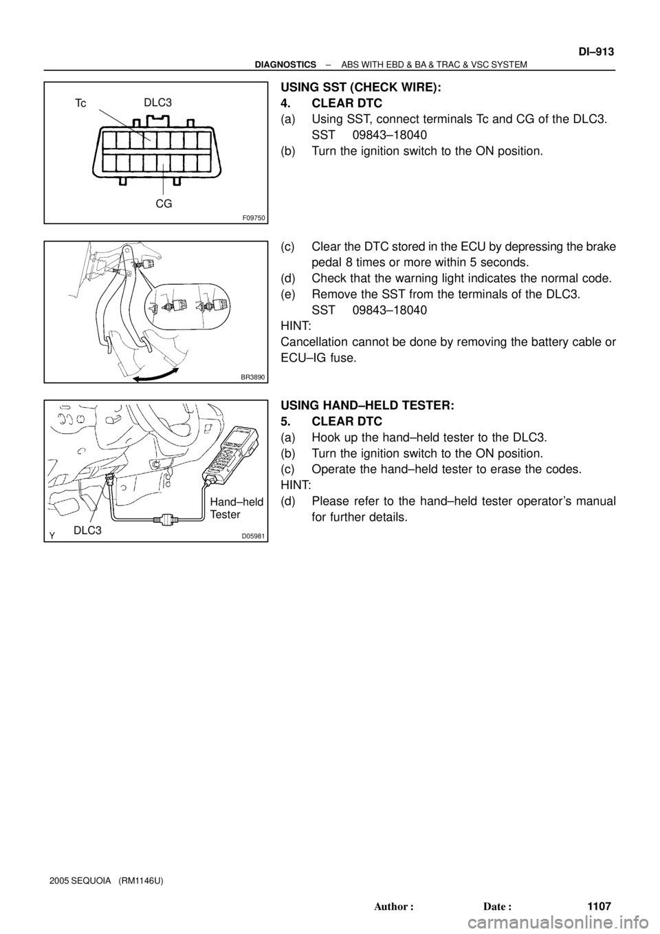
USING SST (CHECK WIRE):
4. CLEAR DTC
(a) Using SST, connect terminals Tc and CG of the DLC3.
SST 09843±18040
(b) Turn the ignition switch to the ON position.
(c) Clear the DTC stored in the ECU by depressing the brake
pedal 8 times or more within 5 seconds.
(d) Check that the warning light indicates the normal code.
(e) Remove the SST from the terminals of the DLC3.
SST 09843±18040
HINT:
Cancellation cannot be done by removing the battery cable or
ECU±IG fuse.
USING HAND±HELD TESTER:
5. CLEAR DTC
(a) Hook up the hand±held tester to the DLC3.
(b) Turn the ignition switch to the ON position.
(c) Operate the hand±held tester to erase the codes.
HINT:
(d) Please refer to the hand±held tester operator's manual
for further details.
Page 1118 of 4323

FAIL±SAFE CHART
1. FAIL SAFE OPERATION
If there is a problem with sensor signals o")
DIDM4±01
DI±916
± DIAGNOSTICSABS WITH EBD & BA & TRAC & VSC SYSTEM
111 0 Author�: Date�:
2005 SEQUOIA (RM1146U)
FAIL±SAFE CHART
1. FAIL SAFE OPERATION
If there is a problem with sensor signals or actuator systems, the skid control ECU prohibits power supply
to the ABS & VSC actuator and informs the ECM of VSC system failure.
The ABS & VSC actuator turns off each solenoid and the ECM shuts off VSC control (traction control signal)
from the skid control ECU accordingly, which turns out to be as if the ABS, VSC and TRAC systems were
not installed.
The ABS, VSC, and TRAC control will be prohibited, but EBD control continues as much as possible. If EBD
control is impossible, the brake warning light comes on to warn the driver (See page DI±910).
MalfunctionSymptom
ABS systemABS, BA, TRAC, and VSC control prohibited
BA systemABS, BA, TRAC, and VSC control prohibited
EBD systemABS & EBD control prohibited
TRAC systemTRAC and VSC control prohibited
VSC systemTRAC and VSC control prohibited
HINT:
�A malfunction in either the ABS or BA system will result in an identical operation, with ABS, BA, TRAC,
and VSC system control prohibited.
�If control is prohibited due to a malfunction during operation, control will be disabled gradually. This
is to avoid sudden vehicle instability.