Page 3717 of 4323
BO47L±04
H24392
Headrest
Headrest
Support
Seatback CoverSeatback Pad
Seatback Frame
Seat Cushion Cover
Seat Cushion Pad
Seat Cushion Frame
Rear No. 2 Seat Inner Belt
Seat AdjusterReclining Connecting Pipe
Reclining Adjuster
Release Handle Reclining Pedal Cover No. 2 Rear Seat
Reclining Cover No. 2 Seat Reclining
Adjuster � Hog Ring
Rear Seat Cushion
Under Cover
Seat Track Handle No. 2 Seat Leg Cover No. 2 Seat Leg Cover� Hog Ring No. 2 Rear Seat
Reclining Cover
N´m (kgf´cm, ft´lbf) : Specified torque
� Non±reusable part
19 (195, 14)
43 (440, 32)
43 (440, 32)
43 (440, 32)
19 (195, 14)
42 (430, 31)
43 (440, 32)
Headrest
Support
Headrest
BO±156
± BODYREAR NO.2 SEAT
3709 Author�: Date�:
2005 SEQUOIA (RM1146U)
REAR NO.2 SEAT
COMPONENTS
HINT:
The procedures listed below are for the LH side.
Page 3718 of 4323
BO47M±02
H16771
± BODYREAR NO.2 SEAT
BO±157
3710 Author�: Date�:
2005 SEQUOIA (RM1146U)
DISASSEMBLY
CAUTION:
Wear safety gloves, because the sharp edges and surfaces
of the seat frame may cause injury to the hands.
HINT:
�The procedures listed below are for the LH side.
�A bolt without a torque specification is shown in the stan-
dard bolt chart (see page SS±2).
1. REMOVE HEADRESTS
2. REMOVE RECLINING ADJUSTER RELEASE HANDLE
3. REMOVE RECLINING PEDAL COVER
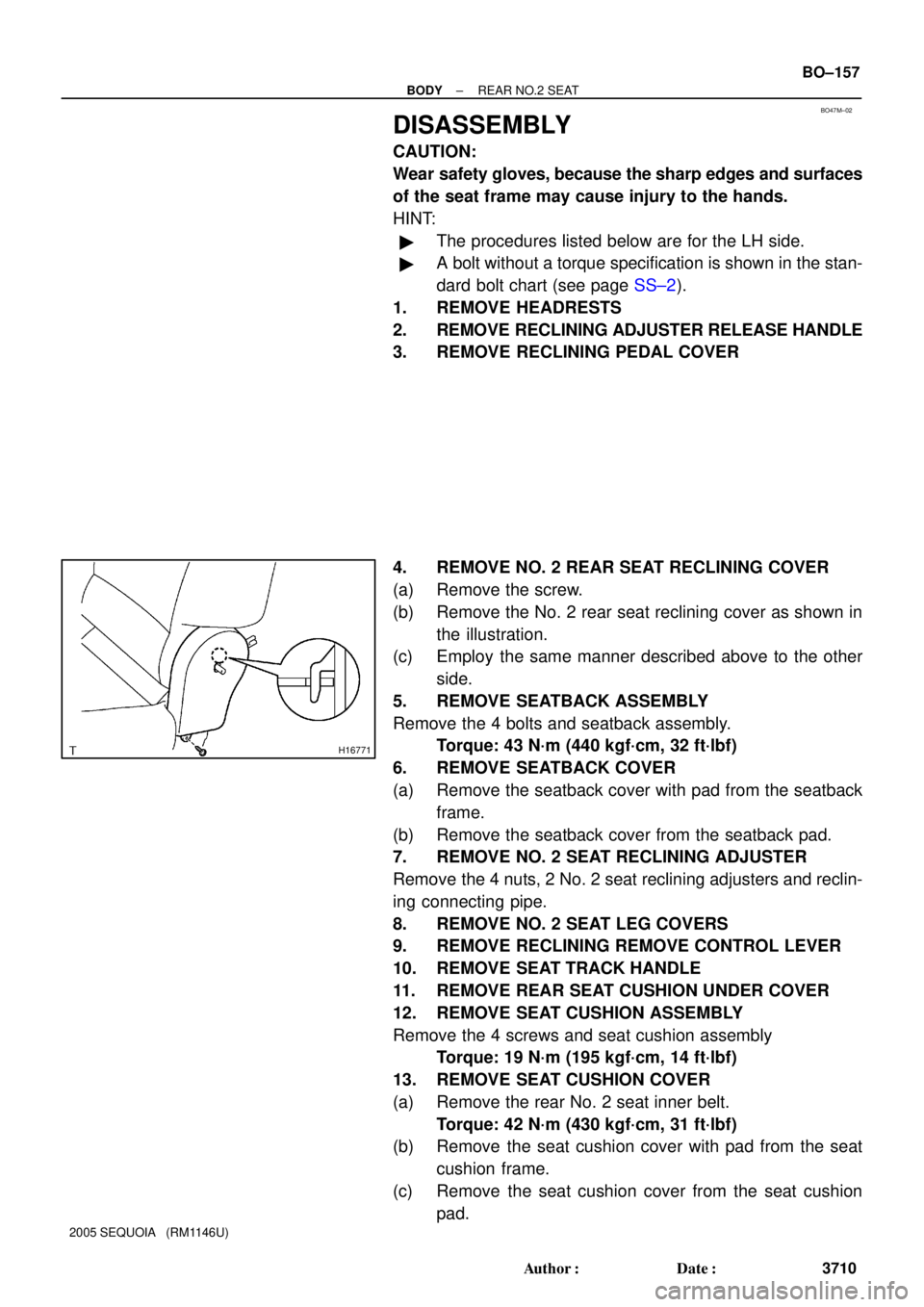
4. REMOVE NO. 2 REAR SEAT RECLINING COVER
(a) Remove the screw.
(b) Remove the No. 2 rear seat reclining cover as shown in
the illustration.
(c) Employ the same manner described above to the other
side.
5. REMOVE SEATBACK ASSEMBLY
Remove the 4 bolts and seatback assembly.
Torque: 43 N´m (440 kgf´cm, 32 ft´lbf)
6. REMOVE SEATBACK COVER
(a) Remove the seatback cover with pad from the seatback
frame.
(b) Remove the seatback cover from the seatback pad.
7. REMOVE NO. 2 SEAT RECLINING ADJUSTER
Remove the 4 nuts, 2 No. 2 seat reclining adjusters and reclin-
ing connecting pipe.
8. REMOVE NO. 2 SEAT LEG COVERS
9. REMOVE RECLINING REMOVE CONTROL LEVER
10. REMOVE SEAT TRACK HANDLE
11. REMOVE REAR SEAT CUSHION UNDER COVER
12. REMOVE SEAT CUSHION ASSEMBLY
Remove the 4 screws and seat cushion assembly
Torque: 19 N´m (195 kgf´cm, 14 ft´lbf)
13. REMOVE SEAT CUSHION COVER
(a) Remove the rear No. 2 seat inner belt.
Torque: 42 N´m (430 kgf´cm, 31 ft´lbf)
(b) Remove the seat cushion cover with pad from the seat
cushion frame.
(c) Remove the seat cushion cover from the seat cushion
pad.
Page 3723 of 4323
BO0633
15°
45°
H05710
40° Rear No.1 Seat
Outer Center
Seat Belt
Retractor
H05731
Rear No.1 Seat
Outer Center
Seat Belt
BO±162
± BODYSEAT BELT
3715 Author�: Date�:
2005 SEQUOIA (RM1146U)
(f) Make sure that the belt can be pulled out at a tilt of 15 de-
grees or less, and cannot be pulled out at over 45 degrees
of tilt.
If a problem is found, replace the assembly.
4. INSPECT REAR NO.1 SEAT CENTER BELT
(a) After extracting 300 mm (11.81 in.), check that the belt is
locked when suddenly extracted.
(b) Check that the belt can be extracted 300 mm (11.81 in.)
without being locked when the seat is reclined as shown
in the illustration.
(c) Check that the belt is locked when the belt is extracted by
a certain amount under (a) condition.
(d) When folding down the seatback forward and extracting
the seat belt slowly, check that the belt is locked after a
certain length (approx. 500 mm (19.69 in.)) of the belt has
been extracted.
Page 3728 of 4323
AB0158
SSTBattery
AB0152
SST
AB0158
SSTBattery
H01580
SST
± BODYSEAT BELT PRETENSIONER
BO±167
3720 Author�: Date�:
2005 SEQUOIA (RM1146U)
1. SEAT BELT PRETENSIONER ACTIVATION WHEN
SCRAPPING VEHICLE
HINT:
Have a battery ready as the power source to activate the seat
belt pretensioner.
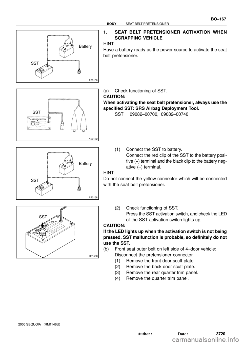
(a) Check functioning of SST.
CAUTION:
When activating the seat belt pretensioner, always use the
specified SST: SRS Airbag Deployment Tool.
SST 09082±00700, 09082±00740
(1) Connect the SST to battery.
Connect the red clip of the SST to the battery posi-
tive (+) terminal and the black clip to the battery neg-
ative (±) terminal.
HINT:
Do not connect the yellow connector which will be connected
with the seat belt pretensioner.
(2) Check functioning of SST.
Press the SST activation switch, and check the LED
of the SST activation switch lights up.
CAUTION:
If the LED lights up when the activation switch is not being
pressed, SST malfunction is probable, so definitely do not
use the SST.
(b) Front seat outer belt on left side of 4±door vehicle:
Disconnect the pretensioner connector.
(1) Remove the front door scuff plate.
(2) Remove the back door scuff plate.
(3) Remove the rear quarter trim panel.
(4) Remove the quarter trim panel.
Page 3773 of 4323
AC3H8±02
I21376
Rear Cooler
Duct Rear Heater Duct
Plate
Rear A/C Unit
Upper Back Door Garnish
Quarter
Pillar
Garnish RH
Rear Seat
Outer Belt
Rear Window
Side Garnish RH
Water Hose
Wire Harness
Suction Tube
Rear Seat
Outer Belt
Rear Quarter Trim
Panel RHBack Door
Scuff Plate
Rear Door Scuff Plate RH
Liquid Tube
� O±Ring
N´m (kgf´cm, in´lbf):Specified torque� Non±reusable part
5.4 (55, 48)
AC±38
± AIR CONDITIONINGREAR A/C UNIT
3765 Author�: Date�:
2005 SEQUOIA (RM1146U)
REAR A/C UNIT
COMPONENTS
Page 3775 of 4323
AC3H9±02
I21380
I21381
AC±40
± AIR CONDITIONINGREAR A/C UNIT
3767 Author�: Date�:
2005 SEQUOIA (RM1146U)
REMOVAL
1. DISCHARGE REFRIGERANT FROM REFRIGERATION
SYSTEM
HINT:
At the time of installation, refer to the following item:
�Evacuate air from the refrigeration system.
�Charge the system with refrigerant and inspect for leak-
age of refrigerant.
Specified amount:
Dual A/C: 1050 ± 50 g (37.03 ± 1.76 oz.)
2. DRAIN ENGINE COOLANT FROM RADIATOR
HINT:
It is not necessary to drain out all coolant.
3. REMOVE REAR SEAT OUTER BELT FLOOR AN-
CHORS
4. REMOVE BACK DOOR SCUFF PLATE
5. REMOVE REAR DOOR SCUFF PLATE RH
6. REMOVE UPPER BACK DOOR GARNISH
7. REMOVE REAR WINDOW SIDE GARNISH RH
8. REMOVE REAR QUARTER TRIM PANEL RH
9. REMOVE QUARTER PILLAR GARNISH RH
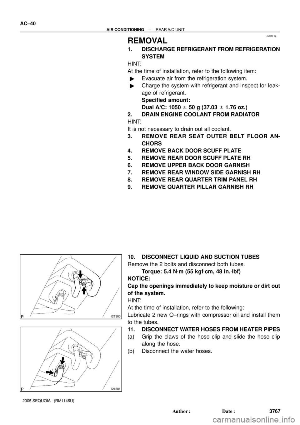
10. DISCONNECT LIQUID AND SUCTION TUBES
Remove the 2 bolts and disconnect both tubes.
Torque: 5.4 N´m (55 kgf´cm, 48 in.´lbf)
NOTICE:
Cap the openings immediately to keep moisture or dirt out
of the system.
HINT:
At the time of installation, refer to the following:
Lubricate 2 new O±rings with compressor oil and install them
to the tubes.
11. DISCONNECT WATER HOSES FROM HEATER PIPES
(a) Grip the claws of the hose clip and slide the hose clip
along the hose.
(b) Disconnect the water hoses.
Page 3806 of 4323
AC3I9±02
I21380
I21383
± AIR CONDITIONINGREAR A/C EVAPORATOR
AC±71
3798 Author�: Date�:
2005 SEQUOIA (RM1146U)
REMOVAL
1. DISCHARGE REFRIGERANT FROM REFRIGERATION
SYSTEM
HINT:
At the time of installation, refer to the following:
�Evacuate air from the refrigeration system.
�Charge the system with refrigerant and inspect for leak-
age of refrigerant.
Specified amount:
Dual A/C: 1050 ± 50 g (37.03 ± 1.76 oz.)
2. DRAIN ENGINE COOLANT FROM RADIATOR
HINT:
It is not necessary to drain out all coolant.
3. REMOVE REAR SEAT OUTER BELT FLOOR AN-
CHORS
4. REMOVE BACKDOOR SCUFF PLATE
5. REMOVE REAR DOOR SCUFF PLATE RH
6. REMOVE UPPER BACK DOOR GARNISH
7. REMOVE REAR WINDOW SIDE GARNISH RH
8. REMOVE REAR QUARTER TRIM PANEL RH
9. REMOVE QUARTER PILLAR GARNISH RH
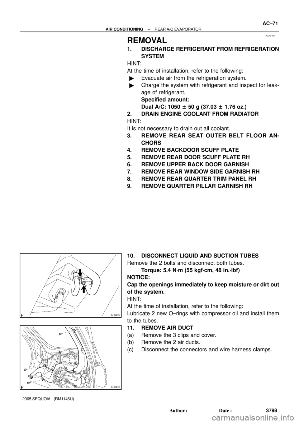
10. DISCONNECT LIQUID AND SUCTION TUBES
Remove the 2 bolts and disconnect both tubes.
Torque: 5.4 N´m (55 kgf´cm, 48 in.´lbf)
NOTICE:
Cap the openings immediately to keep moisture or dirt out
of the system.
HINT:
At the time of installation, refer to the following:
Lubricate 2 new O±rings with compressor oil and install them
to the tubes.
11. REMOVE AIR DUCT
(a) Remove the 3 clips and cover.
(b) Remove the 2 air ducts.
(c) Disconnect the connectors and wire harness clamps.
Page 3809 of 4323
AC3IB±02
I21380
I21383
AC±74
± AIR CONDITIONINGREAR A/C EXPANSION VALVE
3801 Author�: Date�:
2005 SEQUOIA (RM1146U)
REAR A/C EXPANSION VALVE
REMOVAL
1. DISCHARGE REFRIGERANT FROM REFRIGERATION
SYSTEM
HINT:
At the time of installation, refer to the following:
�Evacuate air from the refrigeration system.
�Charge the system with refrigerant and inspect for leak-
age of refrigerant.
Specified amount:
Dual A/C: 1050 ± 50 g (37.03 ± 1.76 oz.)
2. DRAIN ENGINE COOLANT FROM RADIATOR
HINT:
It is not necessary to drain out all coolant.
3. REMOVE REAR SEAT OUTER BELT FLOOR AN-
CHORS
4. REMOVE BACKDOOR SCUFF PLATE
5. REMOVE REAR DOOR SCUFF PLATE RH
6. REMOVE UPPER BACK DOOR GARNISH
7. REMOVE REAR WINDOW SIDE GARNISH RH
8. REMOVE REAR QUARTER TRIM PANEL RH
9. REMOVE QUARTER PILLAR GARNISH RH
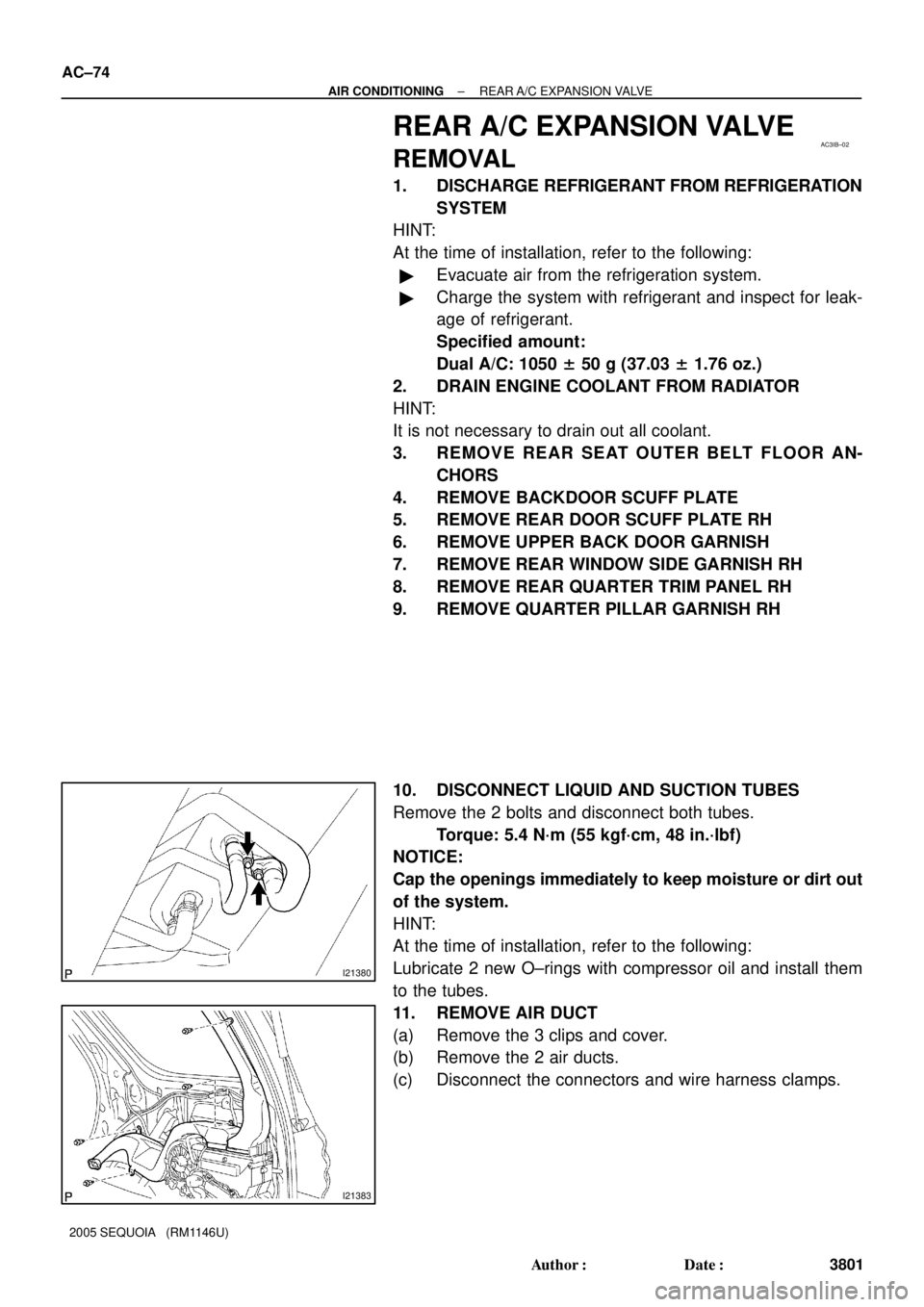
10. DISCONNECT LIQUID AND SUCTION TUBES
Remove the 2 bolts and disconnect both tubes.
Torque: 5.4 N´m (55 kgf´cm, 48 in.´lbf)
NOTICE:
Cap the openings immediately to keep moisture or dirt out
of the system.
HINT:
At the time of installation, refer to the following:
Lubricate 2 new O±rings with compressor oil and install them
to the tubes.
11. REMOVE AIR DUCT
(a) Remove the 3 clips and cover.
(b) Remove the 2 air ducts.
(c) Disconnect the connectors and wire harness clamps.