Page 3386 of 4323

INSTALLATION
HINT:
�Use the same procedures for the RH side and LH si")
RS11N±01
H20066
± SUPPLEMENTAL RESTRAINT SYSTEMSIDE AIRBAG SENSOR ASSEMBLY
RS±95
3378 Author�: Date�:
2005 SEQUOIA (RM1146U)
INSTALLATION
HINT:
�Use the same procedures for the RH side and LH side.
�The procedures listed below are for the LH side.
NOTICE:
�Never use SRS parts from another vehicle. When re-
placing parts, replace them with new ones.
�Never reuse the side airbag sensor assembly in-
volved in a collision when the airbag has deployed.
�If the side airbag sensor assembly center has been
dropped, or there are any cracks, dents or other de-
fects in the case, bracket or connector, replace it with
a new one.
�When installing the side airbag sensor assembly, be
careful that the SRS wiring does not interfere with
other parts and that it is not pinched between other
parts.
�After installing, shake the side airbag sensor assem-
bly to check that there is no looseness.
1. INSTALL SIDE AIRBAG SENSOR ASSEMBLY LH
(a) Install the side airbag sensor assembly LH with the 3
bolts.
Torque: 17.5 N´m (179 kgf´cm, 13 ft´lbf)
(b) Connect the connector to the side airbag sensor assem-
bly LH.
2. INSTALL FRONT SEAT OUTER BELT RETRACTOR
(SEE PAGE BO±172)
3. INSTALL CENTER PILLAR LOWER GARNISH
(SEE PAGE BO±108)
4. INSTALL FRONT SEAT OUTER BELT FLOOR AN-
CHOR (SEE PAGE BO±108 )
5. INSTALL REAR DOOR SCUFF PLATE
(SEE PAGE BO±97)
6. INSTALL FRONT DOOR SCUFF PLATE
(SEE PAGE BO±97)
7. CONNECT CABLE TO NEGATIVE BATTERY TERMI-
NAL
8. PERFORM INITIALIZATION (SEE PAGE BE±77)
Some system need initialization when disconnecting the cable
from the negative battery terminal.
9. INSPECT SRS WARNING LIGHT (SEE PAGE DI±1137)
Page 3388 of 4323

REMOVAL
HINT:
�Use the same procedures for the RH side and L")
RS11P±01
H23905
± SUPPLEMENTAL RESTRAINT SYSTEMCURTAIN SHIELD AIRBAG SENSOR ASSEMBLY
RS±97
3380 Author�: Date�:
2005 SEQUOIA (RM1146U)
REMOVAL
HINT:
�Use the same procedures for the RH side and LH side.
�The procedures listed below are for the LH side.
NOTICE:
�If the wiring connector of the SRS is disconnected
with the ignition switch in the ON position, DTCs will
be recorded.
�Never use airbag parts from another vehicle. When
replacing parts, replace them with new ones.
1. PRECAUTION (SEE PAGE RS±1 and RS±3)
2. DISCONNECT CABLE FROM NEGATIVE BATTERY
TERMINAL
Wait for 90 seconds after disconnecting the cable to prevent the
airbag working.
3. REMOVE REAR SEAT NO. 2 ASSEMBLY
(SEE PAGE BO±157)
4. REMOVE REAR DOOR SCUFF PLATE
(SEE PAGE BO±101)
5. REMOVE REAR FLOOR PANEL SUPPORT PLATE
(SEE PAGE BO±101)
6. REMOVE QUARTER TRIM PLATE
(SEE PAGE BO±101)
7. REMOVE CURTAIN SHIELD AIRBAG SENSOR AS-
SEMBLY LH
(a) Disconnect the curtain shield airbag sensor assembly LH
connector.
NOTICE:
Disconnect the connector with the sensor assembly
installed.
(b) Remove the 2 nuts and curtain shield airbag sensor as-
sembly LH.
Page 3392 of 4323
± SUPPLEMENTAL RESTRAINT SYSTEMCURTAIN SHIELD AIRBAG SENSOR ASSEMBLY
RS±101
3384 Author�: Date�:
2005 SEQUOIA (RM1146U)
8. PERFORM INITIALIZATION (SEE PAGE BE±77)
Some system need initialization when disconnecting the cable
from the negative battery terminal.
9. INSPECT SRS WARNING LIGHT (SEE PAGE DI±1137)
Page 3395 of 4323

REMOVAL
NOTICE:
�If the wiring connector of the SRS is disconnected
with t")
RS0UV±05
RS±104
± SUPPLEMENTAL RESTRAINT SYSTEMSEAT POSITION SENSOR ASSEMBLY
3387 Author�: Date�:
2005 SEQUOIA (RM1146U)
REMOVAL
NOTICE:
�If the wiring connector of the SRS is disconnected
with the ignition switch in the ON position, DTCs will
be recorded.
�Never use SRS parts from another vehicle. When re-
placing the parts, replace them with new ones.
�Never reuse the seat position sensor assembly if the
airbag has previously deployed in a collision.
1. PRECAUTION (SEE PAGE RS±1 and RS±3)
2. DISCONNECT CABLE FROM NEGATIVE BATTERY
TERMINAL
Wait for 90 seconds after disconnecting the cable to prevent the
airbag working.
3. Separate type (Manual adjuster):
REMOVE FRONT SEAT ASSEMBLY LH
(SEE PAGE BO±111)
4. Separate type (Manual adjuster):
REMOVE VERTICAL ADJUSTER HANDLE
(SEE PAGE BO±125)
5. Separate type (Manual adjuster):
REMOVE SEAT CUSHION OUTER SHIELD
(SEE PAGE BO±125)
6. Separate type (Power adjuster):
REMOVE FRONT SEAT ASSEMBLY LH
(SEE PAGE BO±111)
7. Separate type (Power adjuster):
REMOVE SLIDE KNOB AND RECLINING KNOB (SEE
PAGE BO±112)
8. Separate type (Power adjuster):
REMOVE SEAT CUSHION LOWER SHIELD, SEAT
CUSHION OUTER SHIELD AND SEAT CUSHION IN-
NER SHIELD (SEE PAGE BO±112)
Page 3400 of 4323
± SUPPLEMENTAL RESTRAINT SYSTEMSEAT POSITION SENSOR ASSEMBLY
RS±109
3392 Author�: Date�:
2005 SEQUOIA (RM1146U)
6. Separate type (Manual adjuster):
INSTALL SEAT CUSHION OUTER SHIELD
(SEE PAGE BO±130)
7. Separate type (Manual adjuster):
INSTALL VERTICAL ADJUSTER HANDLE
(SEE PAGE BO±130)
8. Separate type (Manual adjuster):
INSTALL FRONT SEAT ASSEMBLY LH
(SEE PAGE BO±134)
9. CONNECT CABLE TO NEGATIVE BATTERY TERMI-
NAL
10. PERFORM INITIALIZATION (SEE PAGE BE±77)
Some system need initialization when disconnecting the cable
from the negative battery terminal.
11. INSPECT SRS WARNING LIGHT (SEE PAGE DI±1137)
Page 3402 of 4323
RS0UV±06
H23938
± SUPPLEMENTAL RESTRAINT SYSTEMOCCUPANT CLASSIFICATION ECU
RS±111
3394 Author�: Date�:
2005 SEQUOIA (RM1146U)
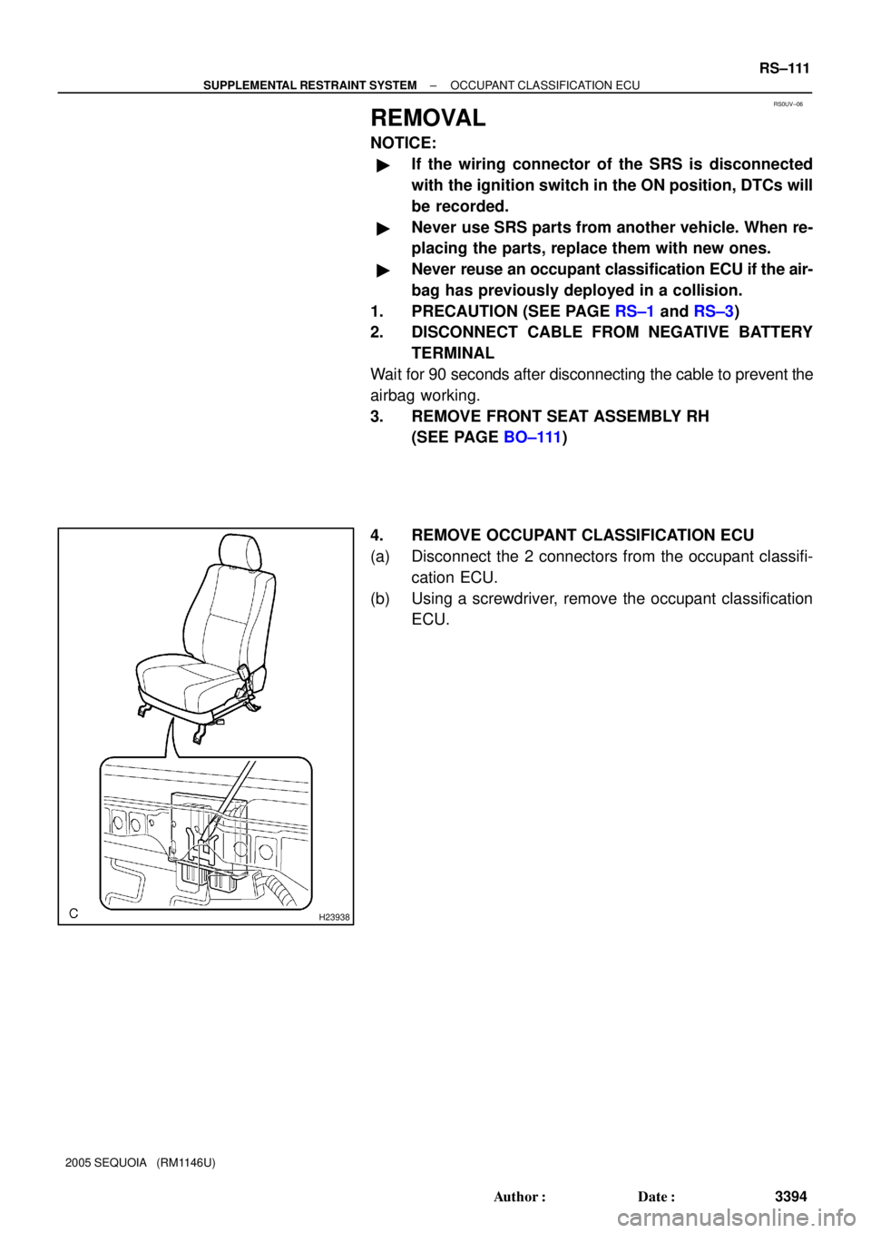
REMOVAL
NOTICE:
�If the wiring connector of the SRS is disconnected
with the ignition switch in the ON position, DTCs will
be recorded.
�Never use SRS parts from another vehicle. When re-
placing the parts, replace them with new ones.
�Never reuse an occupant classification ECU if the air-
bag has previously deployed in a collision.
1. PRECAUTION (SEE PAGE RS±1 and RS±3)
2. DISCONNECT CABLE FROM NEGATIVE BATTERY
TERMINAL
Wait for 90 seconds after disconnecting the cable to prevent the
airbag working.
3. REMOVE FRONT SEAT ASSEMBLY RH
(SEE PAGE BO±111)
4. REMOVE OCCUPANT CLASSIFICATION ECU
(a) Disconnect the 2 connectors from the occupant classifi-
cation ECU.
(b) Using a screwdriver, remove the occupant classification
ECU.
Page 3405 of 4323

INSTALLATION
NOTICE:
�Never use SRS parts from another vehicle. When")
RS0UY±06
H23939
RS±114
± SUPPLEMENTAL RESTRAINT SYSTEMOCCUPANT CLASSIFICATION ECU
3397 Author�: Date�:
2005 SEQUOIA (RM1146U)
INSTALLATION
NOTICE:
�Never use SRS parts from another vehicle. When re-
placing parts, replace them with new ones.
�Never reuse the occupant classification ECU in-
volved in a collision when the airbag has deployed.
�If the occupant classification ECU center has been
dropped, or there are any cracks, dents or other de-
fects in the case, bracket or connector, replace it with
a new one.
�When installing the seat position sensor assembly
center, be careful that the SRS wiring does not inter-
fere with other parts and that it is not pinched be-
tween other parts.
1. INSTALL OCCUPANT CLASSIFICATION ECU
(a) Install the occupant classification ECU.
(b) Connect the 2 connectors to the occupant classification
ECU.
2. INSTALL FRONT SEAT ASSEMBLY RH
(SEE PAGE BO±123)
3. CONNECT CABLE TO NEGATIVE BATTERY TERMI-
NAL
4. PERFORM INITIALIZATION (SEE PAGE BE±77)
Some system need initialization when disconnecting the cable
from the negative battery terminal.
5. INITIALIZE OCCUPANT CLASSIFICATION ECU
(SEE PAGE DI±1137)
6. INSPECT SRS WARNING LIGHT (SEE PAGE DI±1137)
Page 3407 of 4323
H23940Claw
RS11V±01
RS±116
± SUPPLEMENTAL RESTRAINT SYSTEMRSCA OFF SWITCH
3399 Author�: Date�:
2005 SEQUOIA (RM1146U)
REMOVAL
1. PRECAUTION (SEE PAGE RS±1 and RS±3)
2. DISCONNECT CABLE FROM NEGATIVE BATTERY
TERMINAL
Wait for 90 seconds after disconnecting the cable to prevent the
airbag working.
3. REMOVE LOWER FINISH PANEL (SEE PAGE
BO±89)
4. REMOVE SWITCH BASE
(a) Using a screwdriver, release the 3 claws and remover the
switch base.
HINT:
Tape up the screwdriver tip before use.
(b) Disconnect the connectors.