Page 3366 of 4323

(g) Deploy the airbag.
(1) Check that no one is inside the vehicl")
AB0158
Battery
SST
± SUPPLEMENTAL RESTRAINT SYSTEMCURTAIN SHIELD AIRBAG ASSEMBLY
RS±75
3358 Author�: Date�:
2005 SEQUOIA (RM1146U)
(g) Deploy the airbag.
(1) Check that no one is inside the vehicle or within a
10 m (33 ft) radius of the vehicle.
(2) Press the SST activation switch and deploy the air-
bag.
CAUTION:
�When deploying the airbag, make sure that no one is
near the vehicle.
�The curtain shield airbag assembly becomes ex-
tremely hot when the airbag is deployed, so do not
touch it for at least 30 minutes after deployment.
�Use gloves and safety glasses when handling a cur-
tain shield airbag assembly with a deployed airbag.
�Do not apply water, etc. to a curtain shield airbag as-
sembly with a deployed airbag.
�Always wash your hands with water after completing
the operation.
HINT:
The airbag deploys as the LED of the SST activation switch
comes on.
2. DEPLOYMENT WHEN DISPOSING OF CURTAIN
SHIELD AIRBAG ASSEMBLY
NOTICE:
�When disposing of the curtain shield airbag assem-
bly, never use the customer's vehicle to deploy the
airbag.
�Be sure to follow the procedure given below when de-
ploying the airbag.
HINT:
Prepare a battery as the power source to deploy the airbag.
(a) Check the function of the SST (see step 1±(a) on page
RS±23).
(b) Remove the curtain shield airbag assembly (see page
RS±97).
�When removing the front passenger airbag assembly,
work must be started 90 seconds after the ignition
switch is turned to the ºLOCKº position and the nega-
tive (±) terminal cable is disconnected from the bat-
tery.
�When storing the front passenger airbag assembly,
keep the airbag deployment side facing upward.
Page 3368 of 4323

H23917
H2467110 m (33 ft) or more SST
Battery Curtain Shied Airbag Assembly
± SUPPLEMENTAL RESTRAINT SYSTEMCURTAIN SHIELD AIRBAG ASSEMBLY
RS±77
3360 Author�: Dat")
H23928
SST
H23929
Tires
(5 or more)
H23917
H2467110 m (33 ft) or more SST
Battery Curtain Shied Airbag Assembly
± SUPPLEMENTAL RESTRAINT SYSTEMCURTAIN SHIELD AIRBAG ASSEMBLY
RS±77
3360 Author�: Date�:
2005 SEQUOIA (RM1146U)
(e) Install the SST.
After connecting the SST below to each other, connect
them to the curtain shield airbag assembly.
SST 09082±00802 (09082±10801, 09082±20801)
(f) Place tires.
(1) Place at least 2 tires under the tire which the curtain
shield airbag assembly is tied to.
(2) Place at least 2 tires over the tire which the curtain
shield airbag assembly is tied to. The top tire should
have the disc wheel installed.
NOTICE:
Do not place the SST connector under the tire because it
could be damaged.
(3) Tie the tires together with 2 wire harness.
CAUTION:
Make sure that the wire harness is tight. Looseness in the
wire harness results in the tires coming free due to the
shock when the airbag is deployed.
(g) Install the SST.
Connect the SST connector.
SST 09082±00700
NOTICE:
To avoid damaging the SST connector and wire harness,
do not lock the secondary lock of the twin lock. Also, se-
cure some slack for the SST wire harness inside the tire.
(h) Deploy the airbag.
(1) Connect the red clip of the SST to the battery posi-
tive (+) terminal and the black clip of the SST to the
battery negative (±) terminal.
(2) Check that no one is within a 10 m (33 ft) radius of
the tire which the shield airbag assembly is tied to.
Page 3371 of 4323

INSTALLATION
HINT:
�Use the same procedures for the RH side and LH")
RS0TH±07
H23897
RS±80
± SUPPLEMENTAL RESTRAINT SYSTEMCURTAIN SHIELD AIRBAG ASSEMBLY
3363 Author�: Date�:
2005 SEQUOIA (RM1146U)
INSTALLATION
HINT:
�Use the same procedures for the RH side and LH side.
�The procedures listed below are for the LH side.
1. INSTALL CURTAIN SHIELD AIRBAG ASSEMBLY
(a) Install the curtain shield airbag assembly with the 13
bolts.
Torque: 9.8 N´m (100 kgf´cm, 7 ft´lbf)
CAUTION:
Pay attention not to twist the deployment section of the cur-
tain shield airbag assembly.
NOTICE:
�If the curtain shield airbag assembly has been
dropped, or there are cracks, dents or other defects
in the case or connector, replace the curtain shield
airbag assembly with a new one.
�When installing the curtain shield airbag assembly,
take care it is not pinched between other parts.
�Never use airbag parts from another vehicle. When
replacing parts, replace them with new ones.
(b) Connect the connector of the curtain shield airbag as-
sembly.
2. INSTALL ROOF HEADLINING (SEE PAGE BO±108)
3. CONNECT CABLE TO NEGATIVE BATTERY TERMI-
NAL
4. PERFORM INITIALIZATION (SEE PAGE BE±77)
Some system need initialization when disconnecting the cable
from the negative battery terminal.
5. INSPECT SRS WARNING LIGHT (SEE PAGE DI±1137)
Page 3373 of 4323
RS0BL±11
H23231
RS±82
± SUPPLEMENTAL RESTRAINT SYSTEMAIRBAG SENSOR ASSEMBLY
3365 Author�: Date�:
2005 SEQUOIA (RM1146U)
REMOVAL
NOTICE:
�If the wiring connector of the SRS is disconnected
with the ignition switch in the ON position, DTCs will
be recorded.
�Never use airbag parts from another vehicle. When
replacing parts, replace them with new ones.
1. PRECAUTION (SEE PAGE RS±1 and RS±3)
2. DISCONNECT CABLE FROM NEGATIVE BATTERY
TERMINAL
Wait for 90 seconds after disconnecting the cable to prevent the
airbag working.
�Never reuse an airbag sensor assembly if the airbag
has previously deployed in a collision.
3. REMOVE SHIFTING HOLE COVER (SEE PAGE
BO±89)
4. REMOVE UPPER CONSOLE PANEL (SEE PAGE
BO±89)
5. REMOVE REAR CONSOLE BOX (SEE PAGE
BO±89)
6. REMOVE FRONT CONSOLE BOX (SEE PAGE
BO±89)
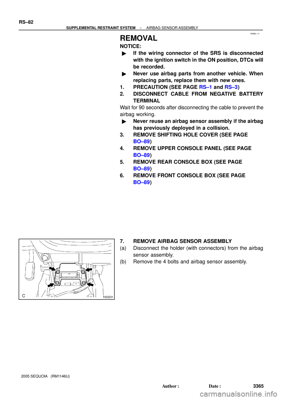
7. REMOVE AIRBAG SENSOR ASSEMBLY
(a) Disconnect the holder (with connectors) from the airbag
sensor assembly.
(b) Remove the 4 bolts and airbag sensor assembly.
Page 3376 of 4323

INSTALLATION
NOTICE:
�Never use SRS parts from another vehicle. When re-
pl")
RS0BO±11
H23231
± SUPPLEMENTAL RESTRAINT SYSTEMAIRBAG SENSOR ASSEMBLY
RS±85
3368 Author�: Date�:
2005 SEQUOIA (RM1146U)
INSTALLATION
NOTICE:
�Never use SRS parts from another vehicle. When re-
placing parts, replace them with new ones.
�Never reuse the airbag sensor assembly involved in
a collision when the airbag has deployed.
�If the airbag sensor assembly center has been
dropped, or there are any cracks, dents or other de-
fects in the case, bracket or connector, replace it with
a new one.
�When installing the airbag sensor assembly center,
be careful that the SRS wiring does not interfere with
other parts and that it is not pinched between other
parts.
�After installing, shake the airbag sensor assembly to
check that there is no looseness.
1. INSTALL AIRBAG SENSOR ASSEMBLY
(a) Install the airbag sensor assembly with the 4 bolts.
Torque: 17.5 N´m (179 kgf´cm, 13 ft´lbf)
(b) Connect the airbag sensor holder (with connectors).
2. INSTALL FRONT CONSOLE BOX ASSEMBLY
(SEE PAGE BO±89)
3. INSTALL REAR CONSOLE BOX ASSEMBLY
(SEE PAGE BO±89)
4. INSTALL UPPER CONSOLE PANEL
(SEE PAGE BO±89)
5. INSTALL SHIFTING HOLE COVER
(SEE PAGE BO±89)
6. CONNECT CABLE TO NEGATIVE BATTERY TERMI-
NAL
7. PERFORM INITIALIZATION (SEE PAGE BE±77)
Some system need initialization when disconnecting the cable
from the negative battery terminal.
8. INSPECT SRS WARNING LIGHT (SEE PAGE DI±1137)
Page 3378 of 4323
RS0TI±03
H23879
± SUPPLEMENTAL RESTRAINT SYSTEMFRONT AIRBAG SENSOR
RS±87
3370 Author�: Date�:
2005 SEQUOIA (RM1146U)
REMOVAL
HINT:
�Use the same procedures for the RH side and LH side.
�The procedures listed below are for the LH side.
NOTICE:
�If the wiring connector of the SRS is disconnected
with the ignition switch in the ON position, DTCs will
be recorded.
�Never use airbag parts from another vehicle. When
replacing parts, replace them with new ones.
�Never reuse a front airbag sensor if the airbag has
previously deployed in a collision.
1. PRECAUTION (SEE PAGE RS±1 and RS±3)
2. DISCONNECT CABLE FROM NEGATIVE BATTERY
TERMINAL
Wait for 90 seconds after disconnecting the cable to prevent the
airbag working.
3. REMOVE FRONT AIRBAG SENSOR LH
(a) Disconnect the front airbag sensor LH connector.
NOTICE:
Disconnect the connector with the sensor assembly
installed.
(b) Remove the 2 nuts and front airbag sensor LH.
Page 3381 of 4323

INSTALLATION
HINT:
�Use the same procedures for the RH side and LH side.
�The")
H23879
RS11I±01
RS±90
± SUPPLEMENTAL RESTRAINT SYSTEMFRONT AIRBAG SENSOR
3373 Author�: Date�:
2005 SEQUOIA (RM1146U)
INSTALLATION
HINT:
�Use the same procedures for the RH side and LH side.
�The procedures listed below are for the LH side.
NOTICE:
�Never use SRS parts from another vehicle. When re-
placing parts, replace them with new ones.
�Never reuse the front airbag sensor involved in a col-
lision when the airbag has deployed.
�If the front airbag sensor center has been dropped, or
there are any cracks, dents or other defects in the
case, bracket or connector, replace it with a new one.
�When installing the front airbag sensor center, be
careful that the SRS wiring does not interfere with
other parts and that it is not pinched between other
parts.
�After installing, shake the front airbag sensor to
check that there is no looseness.
1. INSTALL FRONT AIRBAG SENSORS LH
(a) Install the front airbag sensors LH with the 2 nuts.
Torque: 17.5 N´m (179 kgf´cm, 13 ft´lbf)
(b) Connect the front airbag sensor connectors.
2. CONNECT CABLE TO NEGATIVE BATTERY TERMI-
NAL
3. PERFORM INITIALIZATION (SEE PAGE BE±77)
Some system need initialization when disconnecting the cable
from the negative battery terminal.
4. INSPECT SRS WARNING LIGHT (SEE PAGE DI±1137)
Page 3383 of 4323

REMOVAL
HINT:
�Use the same procedures for the RH side and LH side.
�")
RS11K±01
H20066
RS±92
± SUPPLEMENTAL RESTRAINT SYSTEMSIDE AIRBAG SENSOR ASSEMBLY
3375 Author�: Date�:
2005 SEQUOIA (RM1146U)
REMOVAL
HINT:
�Use the same procedures for the RH side and LH side.
�The procedures listed below are for the LH side.
NOTICE:
�If the wiring connector of the SRS is disconnected
with the ignition switch in the ON position, DTCs will
be recorded.
�Never use airbag parts from another vehicle. When
replacing parts, replace them with new ones.
�Never reuse the side airbag sensor assembly if the
airbag has previously deployed in a collision.
1. PRECAUTION (SEE PAGE RS±1 and RS±3)
2. DISCONNECT CABLE FROM NEGATIVE BATTERY
TERMINAL
Wait for 90 seconds after disconnecting the cable to prevent the
airbag working.
3. REMOVE FRONT DOOR SCUFF PLATE
(SEE PAGE BO±89)
4. REMOVE REAR DOOR SCUFF PLATE
(SEE PAGE BO±89)
5. REMOVE FRONT SEAT OUTER BELT FLOOR AN-
CHOR (SEE PAGE BO±101)
6. REMOVE CENTER PILLAR LOWER GARNISH
(SEE PAGE BO±101)
7. REMOVE FRONT SEAT OUTER BELT RETRACTOR
(SEE PAGE BO±163)
8. REMOVE SIDE AIRBAG SENSOR ASSEMBLY LH
(a) Disconnect the connector from the side airbag sensor as-
sembly LH.
(b) Remove the 3 bolts and the side airbag sensor assembly
LH.