Page 3098 of 4323
SA17R±04
F14272
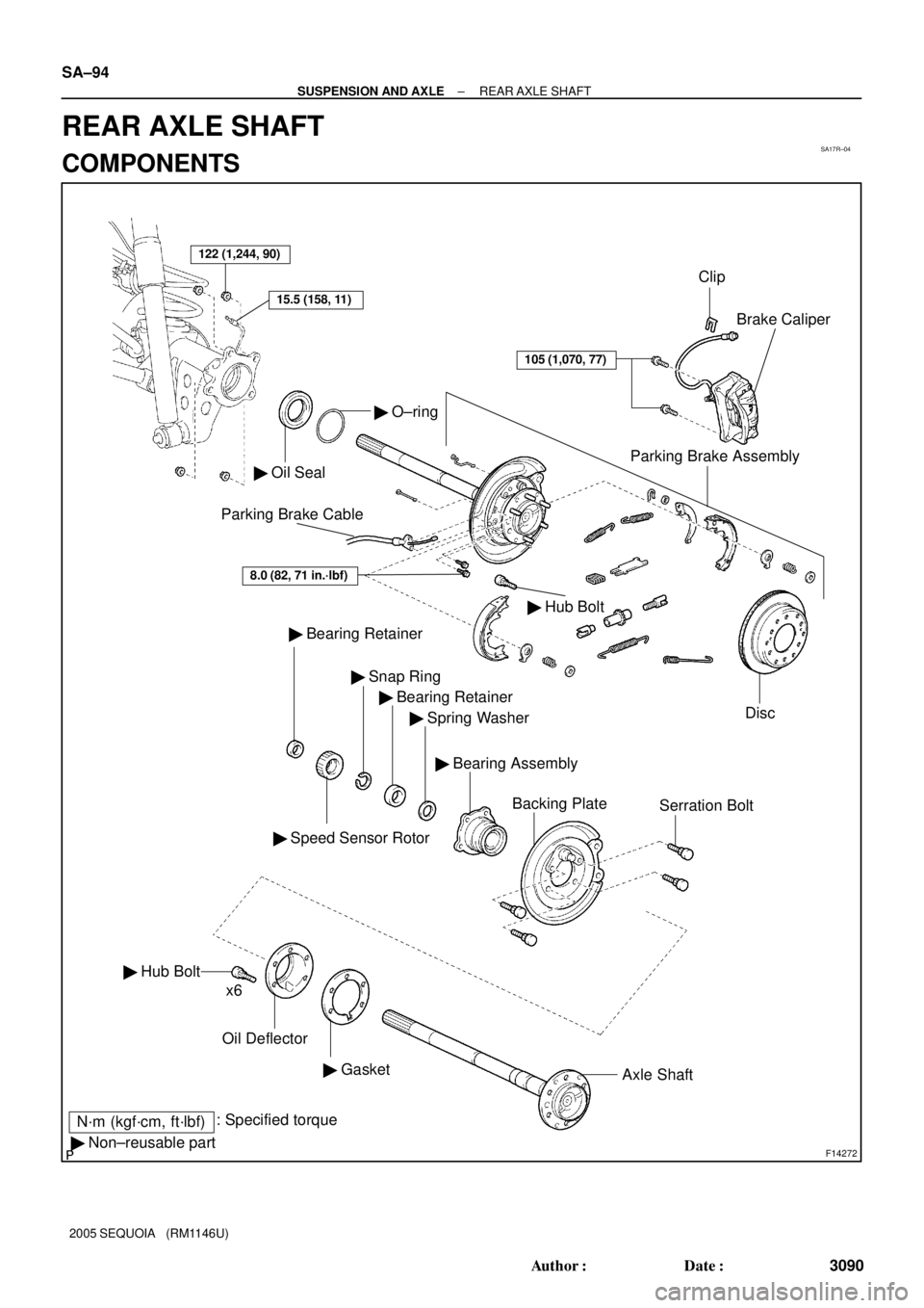
122 (1,244, 90)
� Oil Seal
� O±ring
Parking Brake Assembly
Disc Brake Caliper
� Bearing Retainer
� Speed Sensor Rotor
� Snap Ring
� Bearing Retainer
� Spring Washer
Backing PlateSerration Bolt
� Hub Bolt
Oil Deflector
� GasketAxle Shaft
N´m (kgf´cm, ft´lbf): Specified torque
� Non±reusable partx6
105 (1,070, 77)
15.5 (158, 11)
Clip
Parking Brake Cable
� Hub Bolt
8.0 (82, 71 in.´lbf)
� Bearing Assembly SA±94
± SUSPENSION AND AXLEREAR AXLE SHAFT
3090 Author�: Date�:
2005 SEQUOIA (RM1146U)
REAR AXLE SHAFT
COMPONENTS
Page 3106 of 4323
SA17X±07
SA±102
± SUSPENSION AND AXLEREAR AXLE SHAFT
3098 Author�: Date�:
2005 SEQUOIA (RM1146U)
INSTALLATION
Installation is in the reverse order of removal (See page SA±95).
HINT:
After installation, fill the brake reservoir with brake fluid, bleed the brake system (See page BR±4), check
for leaks and check the speed sensor signal (See page DI±899).
Page 3150 of 4323
SA17B±05
F14298
Speed Sensor
Wire Harness
Lower Control Arm
N´m (kgf´cm, ft´lbf) : Specified torque
Upper Control Arm
140 (1,428, 103)
140 (1,428, 103)
28 (286, 21)
130 (1,326, 96)
26 (265, 19)
Parking Brake Cable130 (1,326, 96)
Brake Line
Bracket
SA±146
± SUSPENSION AND AXLEREAR UPPER AND LOWER CONTROL ARM
3142 Author�: Date�:
2005 SEQUOIA (RM1146U)
REAR UPPER AND LOWER CONTROL ARM
COMPONENTS
Page 3151 of 4323
SA24J±02
F14299
F14300
± SUSPENSION AND AXLEREAR UPPER AND LOWER CONTROL ARM
SA±147
3143 Author�: Date�:
2005 SEQUOIA (RM1146U)
REMOVAL
1. REMOVE REAR WHEEL
Torque: 110 N´m (1,150 kgf´cm, 83 ft´lbf)
2. SUPPORT REAR AXLE HOUSING WITH JACK
3. REMOVE UPPER CONTROL ARM
(a) Disconnect the speed sensor wire harness.
(b) Remove the bolt and brake line bracket.
Torque: 28 N´m (286 kgf´cm, 21 ft´lbf)
(c) Remove the 2 nuts, washers, bolts and upper control arm.
Torque: 140 N´m (1,428 kgf´cm, 103 ft´lbf)
HINT:
At the time of installation, after stabilizing the suspension,
torque the nuts.
4. REMOVE LOWER CONTROL ARM
(a) Remove the bolt and parking brake cable bracket.
Torque: 26 N´m (265 kgf´cm, 19 ft´lbf)
(b) Remove the 2 nuts, bolts and lower control arm.
Torque: 130 N´m (1,326 kgf´cm, 96 ft´lbf)
HINT:
At the time of installation, after stabilizing the suspension,
torque the nuts.
Page 3190 of 4323
BR10E±04
F16310
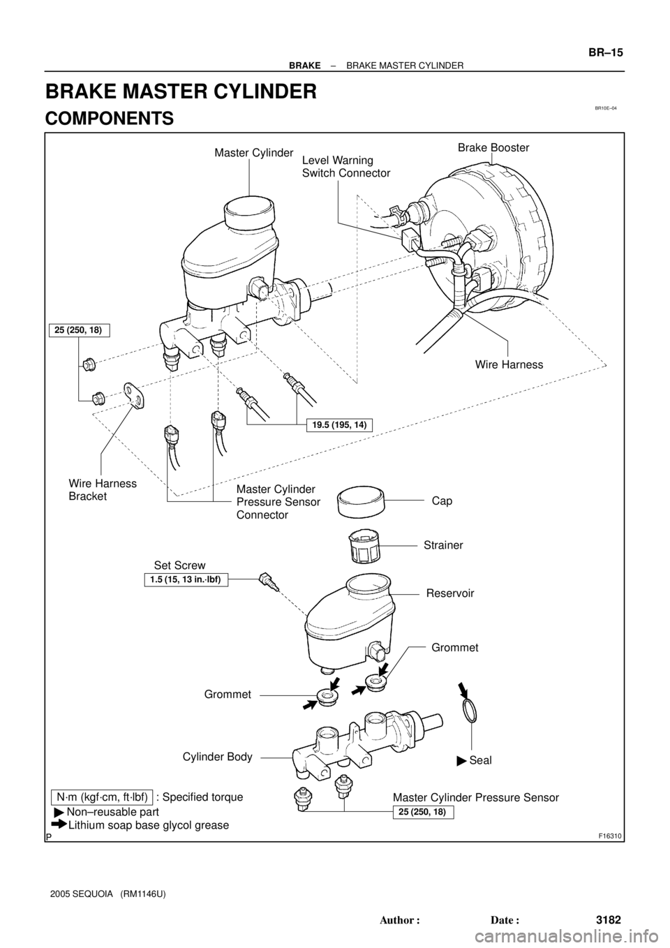
Master Cylinder
Level Warning
Switch ConnectorBrake Booster
Cap
Strainer
Reservoir Set Screw
Grommet
Cylinder Body
N´m (kgf´cm, ft´lbf) : Specified torque
� Non±reusable part
Lithium soap base glycol greaseWire Harness
BracketMaster Cylinder
Pressure Sensor
Connector
Master Cylinder Pressure Sensor� Seal
25 (250, 18)
25 (250, 18)
19.5 (195, 14)
Wire Harness
1.5 (15, 13 in.´lbf)
Grommet
± BRAKEBRAKE MASTER CYLINDER
BR±15
3182 Author�: Date�:
2005 SEQUOIA (RM1146U)
BRAKE MASTER CYLINDER
COMPONENTS
Page 3191 of 4323
BR08U±05
F16312
F16313
BR±16
± BRAKEBRAKE MASTER CYLINDER
3183 Author�: Date�:
2005 SEQUOIA (RM1146U)
REMOVAL
1. DRAW OUT FLUID WITH SYRINGE
NOTICE:
Wash the brake fluid off immediately if it comes into con-
tact with any painted surface.
2. DISCONNECT LEVEL WARNING SWITCH CONNEC-
TOR
3. DISCONNECT 2 MASTER CYLINDER PRESSURE
SENSOR CONNECTORS
4. DISCONNECT WIRE HARNESS
Using a clip remover, disconnect the wire harness from the wire
harness bracket.
5. DISCONNECT BRAKE LINES
Using SST, disconnect the 2 brake lines from the master cylin-
der.
SST 09023±38201
Torque: 19.5 N´m (195 kgf´cm, 14 ft´lbf)
6. REMOVE MASTER CYLINDER
(a) Remove the 2 nuts and wire harness bracket.
Torque: 25 N´m (250 kgf´cm, 18 ft´lbf)
(b) Pull out the master cylinder from the brake booster.
Page 3192 of 4323
BR1ND±02
± BRAKEBRAKE MASTER CYLINDER
BR±17
3184 Author�: Date�:
2005 SEQUOIA (RM1146U)
DISASSEMBLY
1. REMOVE RESERVOIR
(a) Remove the set screw and pull out the reservoir.
Torque: 1.5 N´m (15 kgf´cm, 13 in.´lbf)
(b) Remove the cap and strainer from the reservoir.
2. REMOVE 2 GROMMETS
3. REMOVE SEAL
4. REMOVE 2 MASTER CYLINDER PRESSURE SENSORS
Torque: 25 N´m (250 kgf´cm, 18 ft´lbf)
Page 3194 of 4323
BR08Y±07
± BRAKEBRAKE MASTER CYLINDER
BR±19
3186 Author�: Date�:
2005 SEQUOIA (RM1146U)
INSTALLATION
Installation is in the reverse order of removal (See page BR±16).
HINT:
�After installation, fill the brake reservoir with brake fluid and bleed brake system (See page BR±4).
�Check for leaks.
NOTICE:
In case of replacing the master cylinder assembly or master cylinder pressure sensor, perform the
zero point calibration of the steering angle, master cylinder pressure, yawrate and deceleration sen-
sors (See page DI±897).
 : Specified torque
Upper Control Arm
140 (1,428, 103)
140 (1,428, 103)
28 (286, 21)
130 (1,326, 96)
26 (265, 19)
Pa")