Page 1671 of 1943

REMOVAL
1. REMOVE FRONT WHEEL
Torque: 103 N´m (1,050 kgf´cm, 76 ft´lbf)
2. RE")
SA1ZW±01
F11576
SST
F11616
F11617
F11586
± SUSPENSION AND AXLEFRONT LOWER SUSPENSION ARM
SA±33
2001 PRIUS (RM778U)
REMOVAL
1. REMOVE FRONT WHEEL
Torque: 103 N´m (1,050 kgf´cm, 76 ft´lbf)
2. REMOVE ENGINE UNDER COVER
3. REMOVE LOWER SUSPENSION ARM
(a) Disconnect the RH and LH tie rod ends.
(1) Remove the cotter pin and nut.
Torque: 49 N´m (500 kgf´cm, 36 ft´lbf)
(2) Using SST, disconnect the tie rod end from the
steering knuckle.
SST 09628±62011
(3) Employ the same manner described above to the
other side.
(b) Disconnect the RH and LH stabilizer bar links.
(1) Remove the nut and disconnect the stabilizer bar
link from the shock absorber.
Torque: 74 N´m (755 kgf´cm, 55 ft´lbf)
HINT:
If the ball joint turns together with the nut, use a hexagon (5 mm)
wrench to hold the stud.
(2) Employ the same manner described above to the
other side.
(c) Disconnect the RH and LH lower suspension arms from
the lower ball joints.
(1) Remove the bolt and 2 nuts, and disconnect the
lower suspension arm from the lower ball joint.
Torque: 142 N´m (1,450 kgf´cm, 105 ft´lbf)
(2) Employ the same manner described above to the
other side.
(d) Loosen the 2 lower suspension arm set bolts.
Torque: 137 N´m (1,397 kgf´cm, 101 ft´lbf)
HINT:
At the time of installation, after stabilizing the suspension,
torque the bolts.
(e) Disconnect the sliding yoke (See page SR±6).
(f) Support the suspension member with a transmission
jack.
Page 1672 of 1943
F12936
F12933
SA±34
± SUSPENSION AND AXLEFRONT LOWER SUSPENSION ARM
2001 PRIUS (RM778U)
(g) Remove the bolt and nut, disconnect the torque rod from
the suspension member.
Torque: 100 N´m (1,150 kgf´cm, 83 ft´lbf)
(h) Remove the 4 bolts and disconnect the suspension mem-
ber from the body.
Torque:
Front side: 113 N´m (1,152 kgf´cm, 83 ft´lbf)
Rear side: 157 N´m (1,600 kgf´cm, 116 ft´lbf)
(i) Remove the 2 lower suspension arm set bolts and discon-
nect the lower suspension arm from suspension member.
Page 1673 of 1943
SA1ZU±01
F11598
SST
F11599
F11593
Wood
F11618
± SUSPENSION AND AXLEREAR SHOCK ABSORBER
SA±51
2001 PRIUS (RM778U)
REMOVAL
1. REMOVE REAR WHEELS
Torque: 103 N´m (250 kgf´cm, 18 ft´lbf)
2. REMOVE REAR SEAT (See page BO±83)
3. DISCONNECT BRAKE LINES
(a) Using SST, disconnect the brake lines from the flexible
hose. Use a container to catch brake fluid as it drains out.
SST 09751±36011
(b) Remove the clip.
(c) Employ the same manner described above to the other
side.
4. DISCONNECT ABS SPEED SENSOR WIRE HARNESS
Remove the 4 nuts, and disconnect the ABS speed sensor wire
harness from the axle beam.
Torque: 5.4 N´m (55 kgf´cm, 48 in.´lbf)
5. SUPPORT REAR AXLE BEAM AT RIGHT AND LEFT
SIDES WITH JACKS
6. REMOVE SHOCK ABSORBER
(a) Remove the 2 nuts and bolt.
Torque: 80 N´m (816 kgf´cm, 59 ft´lbf)
Page 1674 of 1943
F11619
SA±52
± SUSPENSION AND AXLEREAR SHOCK ABSORBER
2001 PRIUS (RM778U)
(b) Remove the nut, washer and shock absorber.
Torque: 80 N´m (816 kgf´cm, 59 ft´lbf)
Page 1675 of 1943

REPLACEMENT
1. REMOVE TOE CONTROL LINK
(a) Remove the nut.
(b) Using a brass bar, remov")
SA1ZV±01
F11600
F11601
SST
F11602
SST
F11603
SA±60
± SUSPENSION AND AXLEREAR AXLE BEAM
2001 PRIUS (RM778U)
REPLACEMENT
1. REMOVE TOE CONTROL LINK
(a) Remove the nut.
(b) Using a brass bar, remove the bolt.
(c) Using a SST, remove the toe control link from axle beam.
SST 09710±40010 (09711±40010, 09712±40010),
09727±30021 (09727±00010, 09727±00031)
NOTICE:
�Make sure that the arm inside of SST is contact with
the toe control link at the position shown in the il-
lustration.
�Never use SST (09727 ± 00030)
HINT:
The outer race of the toe control link is made of rubber and be-
cause of its elasticity, it is difficult to remove the link from the axle
beam.
So, tap the part indicated by the arrow with a plastic hammer
when removing.
2. INSTALL TOE CONTROL LINK
(a) Using a SST, install a new toe control link.
SST 09710±40010 (09711±40010, 09712±40010),
09727±30021 (09727±00010, 09727±00031)
NOTICE:
�Make sure that the arm inside of SST is contact with
the frange of the toe control link.
�Align the bolt holes of the toe control link and axle
beam in the direction of press±fitting.
When the bolt holes slip off the aligned position,
press±fit a new toe control link again.
HINT:
�Until the outer race is fit into the axle beam, adjust the arm
position of SST to set the toe control link upright to the
axle beam.
�When the toe control link is fully press±fit into the axle
beam, the bolt holes are not aligned.
Page 1676 of 1943
F11604
± SUSPENSION AND AXLEREAR AXLE BEAM
SA±61
2001 PRIUS (RM778U)
(b) Using a extension bar and press, install a new bolt.
NOTICE:
Press in the bolt until the base of the bolt head is pressed
tightly against the axle beam.
(c) Install the a nut.
Page 1710 of 1943
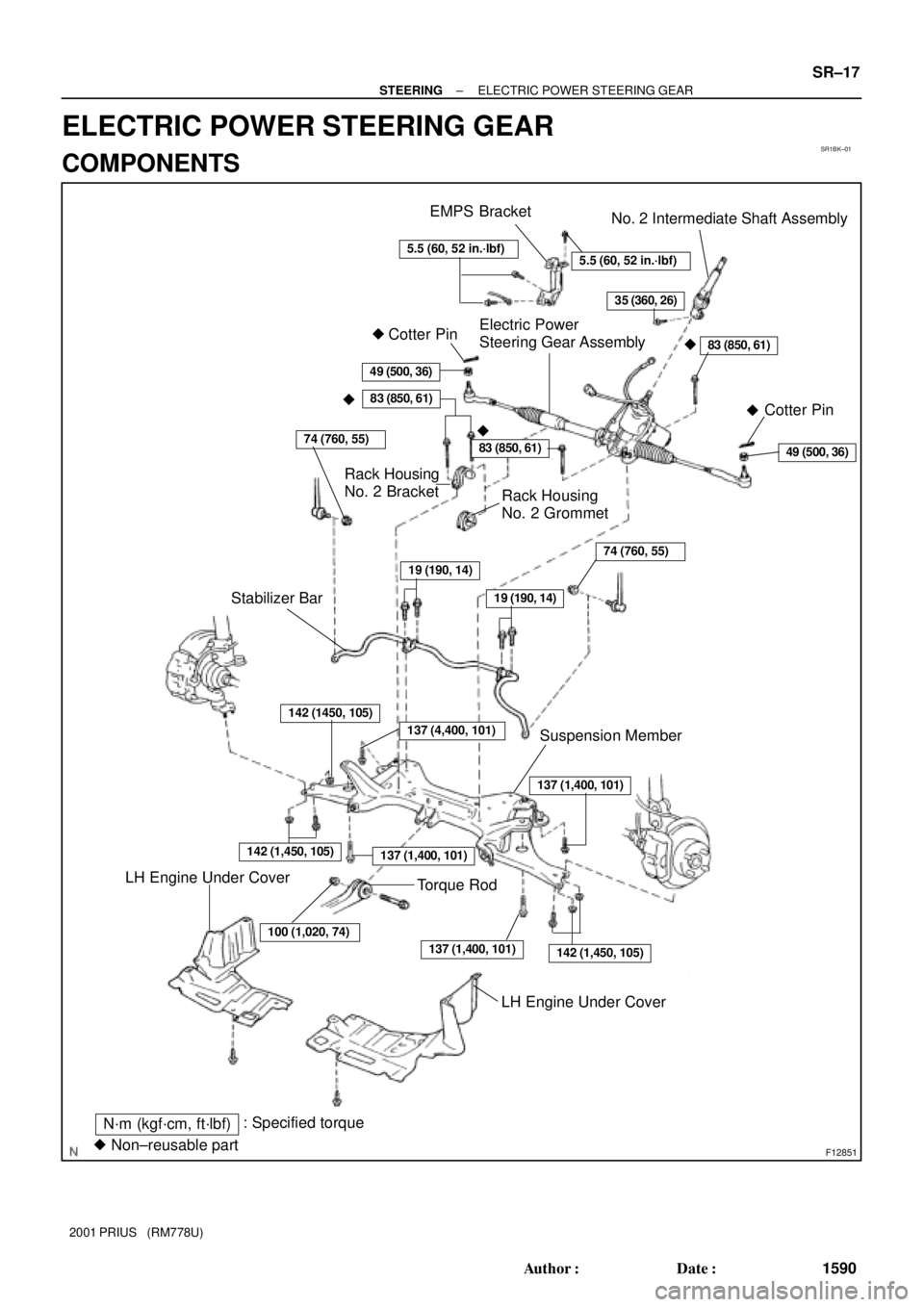
SR1BK±01
F12851
No. 2 Intermediate Shaft Assembly
�Cotter Pin
N´m (kgf´cm, ft´lbf): Specified torque
� Non±reusable part
74 (760, 55)
35 (360, 26)
83 (850, 61)
49 (500, 36)
�Cotter PinElectric Power
Steering Gear Assembly
Rack Housing
No. 2 Grommet
Rack Housing
No. 2 Bracket
83 (850, 61)
83 (850, 61)
74 (760, 55)
19 (190, 14)
19 (190, 14)Stabilizer Bar
142 (1450, 105)
142 (1,450, 105)
100 (1,020, 74)
137 (1,400, 101)
137 (1,400, 101)142 (1,450, 105)
137 (1,400, 101)
Suspension Member
LH Engine Under Cover
LH Engine Under Cover
49 (500, 36)
137 (4,400, 101)
Torque Rod
5.5 (60, 52 in.´lbf)5.5 (60, 52 in.´lbf)
EMPS Bracket
�
��
± STEERINGELECTRIC POWER STEERING GEAR
SR±17
1590 Author�: Date�:
2001 PRIUS (RM778U)
ELECTRIC POWER STEERING GEAR
COMPONENTS
Page 1712 of 1943

REMOVAL
NOTICE:
Remove the steering wheel assembly before the steering
gear removal, because there is p")
SR1BL±01
F12196
F12214
A
B
± STEERINGELECTRIC POWER STEERING GEAR
SR±19
2001 PRIUS (RM778U)
REMOVAL
NOTICE:
Remove the steering wheel assembly before the steering
gear removal, because there is possibility of breaking of
the spiral cable.
1. PLACE FRONT WHEELS FACING STRAIGHT AHEAD
2. REMOVE STEERING WHEEL PAD (See page SR±6)
3. REMOVE STEERING WHEEL (See page SR±6)
4. REMOVE RH AND LH ENGINE UNDER COVERS
5. DISCONNECT RH AND LH TIE ROD ENDS (See page
SA±9)
6. DISCONNECT STABILIZER BAR (See page SA±41)
7. DISCONNECT LOWER SUSPENSION ARM FROM
LOWER BALL JOINT (See page SA±41)
8. DISCONNECT 2 CONNECTORS AND EMPS BRACK-
ET
(a) Disconnect the 2 connectors.
(b) Disconnect the 2 clamps.
(c) Remove the bolt and disconnect the earth wire.
(d) Remove the 2 bolts and EMPS bracket.
9. DISCONNECT NO. 2 INTERMEDIATE SHAFT AS-
SEMBLY
(a) Place the matchmarks on the No. 2 intermediate shaft as-
sembly and control valve shaft.
(b) Loosen the bolt ºAº and remove the bolt ºBº then discon-
nect the No. 2 intermediate shaft assembly from the con-
trol valve shaft.
10. DISCONNECT TORQUE ROD (See page SA±41)
11. REMOVE SUSPENSION MEMBER AND ELECTRIC
POWER STEERING GEAR ASSEMBLY (See page
SA±41)
12. REMOVE ELECTRIC POWER STEERING GEAR AS-
SEMBLY
(a) Remove the stabilizer bar (See page SA±41).

(g) Remove the bolt and nut, disconnect the torque rod from
the suspension member.
Torque: 100 N´m (1,150 k")

REMOVAL
1. REMOVE REAR WHEELS
Torque: 103 N´m (250 kgf´cm, 18 ft´lbf)
2. REMOVE")

(b) Remove the nut, washer and shock absorber.
Torque: 80 N´m (816 kgf´cm, 59 ft´lbf)")

(b) Using a extension bar and press, install a new bolt.
NOTICE:
Press in the bolt until the base of the bolt head is pressed")