Page 579 of 1943
SS0MG±01
SS±4
± SERVICE SPECIFICATIONSMAINTENANCE
126 Author�: Date�:
2001 PRIUS (RM778U)
MAINTENANCE
SERVICE DATA
Front axle and suspension
Ball joint vertical play Maximum
0 mm (0 in.)
Page 580 of 1943
SS0MH±04
± SERVICE SPECIFICATIONSMAINTENANCE
SS±5
2001 PRIUS (RM778U)
TORQUE SPECIFICATION
Part tightenedN´mkgf´cmft´lbf
Front seat x Body3737527
Front suspension member x Body Bolt A11 31,15283Front sus ension member x Body Bolt A
(See page MA±7) Bolt B
11 3
157
1,152
1,600
83
11 6
Rear suspension member x Body9091866
Page 601 of 1943

SS13W±06
SS±26
± SERVICE SPECIFICATIONSSUSPENSION AND AXLE
148 Author�: Date�:
2001 PRIUS (RM778U)
SUSPENSION AND AXLE
SERVICE DATA
Cold tire inflation
pressureTire size: P175/65R14 84S Front
Rear240 kPa (2.4 kgf/cm2, 35 psi)
230 kPa (2.3 kgf/cm2, 33 psi)
Vehicle height
P175/65R14Front*1
Rear*2191 mm (7.52 in.)
239 mm (9.41 in.)
Camber
Right±left error±0°26' ± 45' (±0.43° ± 0.75°)
45' (0.75°) or less
Front wheel
Caster
Right±left error1°02' ± 45' (1.03° ± 0.75°)
45' (0.75°) or less
Front wheel
alignmentSteering axis inclination
Right±left error9°52' ± 45' (9.87° ± 0.75°)
45' (0.75°) or less
Toe±in (total)
Rack end length difference0°06' ± 12' (0.1° ± 0.2°, 1 ± 2 mm, 0.04± 0.08 in.)
1.5 mm (0.059 in.) or less
Wheel angle
Inside wheel
Outside wheel: Reference
42°42' ± 2° (42.70° ± 2°)
35°54' (35.90°)
Rear wheel
Camber
Right±left error±1°30' ± 45' (±0.93° ± 0.75°)
45' (0.75°) or less
Rear wheel
alignmentToe±in (total)0°06' ± 20' (0.1° ± 0.33°)
1 ± 3.0 mm (0.04 ± 0.12 in.)
FtlAxle bearing backlash Maximum0.05 mm (0.0020 in.)Front axleAxle hub deviationMaximum0.07 mm (0.0028 in.)
Front drive shaftDrive shaft standard length LH
RH579.9 ± 5.0 mm (22.831 ± 0.197 in.)
836.9 ± 5.0 mm (32.949 ± 0.197 in.)
Ft iLower suspension arm ball joint turning torque1.0 ± 4.9 N´m (10 ± 50 kgf´cm, 8.7 ± 43 in.´lbf)Front suspensionStabilizer bar link ball joint turning torque0.05 ± 1.0 N´m (0.5 ± 10 kgf´cm, 0.4 ± 8.7 in.´lbf)
RlAxle bearing backlash Maximum0.05 mm (0.0020 in.)Rear axleAxle hub deviationMaximum0.07 mm (0.0028 in.)
*1: Front measuring point
Measure the distance from the ground to the head center of the front side lower suspension arm mounting
bolt.
*2: Rear measuring point
Measure the distance from the ground to the center of the rear axle beam mounting bolt.
Page 602 of 1943

SS04X±12
± SERVICE SPECIFICATIONSSUSPENSION AND AXLE
SS±27
2001 PRIUS (RM778U)
TORQUE SPECIFICATION
Part tightenedN´mkgf´cmft´lbf
FRONT AXLE
Hub nut1031,05076
Tie rod end lock nut7475055
Steering knuckle x Shock absorber1531,56011 3
Steering knuckle x Brake caliper1071,09079
Steering knuckle x Tie rod end4950036
Axle hub x Drive shaft2162,200159
Lower ball joint x Lower suspension arm1421,450105
Lower ball joint x Steering knuckle1031,05076
Steering knuckle x Dust cover8.38574 in.´lbf
ABS speed sensor set bolt8.08271 in.´lbf
FRONT SUSPENSION
Suspension support x Body3940029
Suspension support x Piston rod4747534
Flexible hose x Shock absorber2930022
ABS speed sensor wire harness x Shock absorber5.45548 in.´lbf
Lower suspension arm set bolt1371,397101
Suspension member set bolt Front side
Rear side11 3
1571,152
1,60083
11 6
Torque rod x Suspension member1001,03074
Stabilizer bar bracket x Suspension member1919414
Stabilizer bar link set nut7475555
REAR AXLE
Hub nut1031,05076
Axle hub set bolt5252538
REAR SUSPENSION
Shock absorber x Axle Beam8081659
ABS speed sensor wire harness x Axle Beam5.45548 in.´lbf
Spring bracket x Body8081659
Shock absorber center nut5657141
Parking brake cable set bolt5.45548 in.´lbf
Toe control link x Body9091866
Toe control link x Axle beam9091866
Stabilizer bar set bolt1491,51911 0
Page 606 of 1943

SS16Z±08
± SERVICE SPECIFICATIONSSTEERING
SS±31
2001 PRIUS (RM778U)
TORQUE SPECIFICATION
Part tightenedN´mkgf´cmft´lbf
TILT STEERING COLUMN
Adjusting nut131309
No. 2 tilt lever lock bolt5.45548 in.´lbf
Tilt steering support lock nut9.510087 in.´lbf
Main shaft lower dust seal4.95043 in.´lbf
Column assembly set bolt and nut2526019
No. 2 intermediate shaft assembly x Main shaft assembly3536026
No. 2 intermediate shaft assembly x Intermediate extension3536026
Shift lock computer sub±assembly4.04035 in.´lbf
Steering wheel set nut5051037
Steering wheel pad set screw (Torx screw)8.89078 in.´lbf
POWER STEERING GEAR
Rack end x Steering rack62 (83)630 (850)46 (61)
Tie rod end lock nut5657041
PS gear assembly set bolt8385061
Stabilizer bar set bolt1919014
Suspension member137
1421,400
1,450101
105
Torque rod set nut1001,02074
EMPS bracket set bolt5.56052 in.´lbf
Lower suspension arm x Lower ball joint1421,450105
Stabilizer bar link set nut7476055
Tie rod end x Steering knuckle4950036
( ): For use without SST
Page 1513 of 1943
A13910
A13911
A13912
A13913
A13914
± ENGINE MECHANICALENGINE UNIT
EM±55
2001 PRIUS (RM778U)
23. DISCONNECT TIE ROD END FROM STEERING
KNUCKLE (See page SA±9)
24. DISCONNECT STABILIZER BAR LINK
Remove the nut and disconnect the stabilizer bar link from the
suspension member.
25. DISCONNECT BALL JOINT FROM LOWER ARM
Remove the 2 bolts and 4 nuts, disconnect the ball joint.
26. REMOVE DRIVE SHAFTS (See page SA±17)
27. REMOVE TORQUE ROD
Remove the 4 bolts and 2 nuts and torque rod from the body.
28. REMOVE SUSPENSION MEMBER
Remove the 4 bolts and disconnect the suspension member
from the body.
29. SET ENGINE JACK
NOTICE:
Using chain, hold the engine tightly.
30. DISCONNECT ENGINE MOUNTINGS
(a) Remove the 2 bolts, 2 nuts and disconnect the RH engine
mounting insulator from the bracket.
Page 1516 of 1943

A13913
A13914
A13912
AB
B
A
A13911
A13910
± ENGINE MECHANICALENGINE UNIT
EM±59
2001 PRIUS (RM778U)
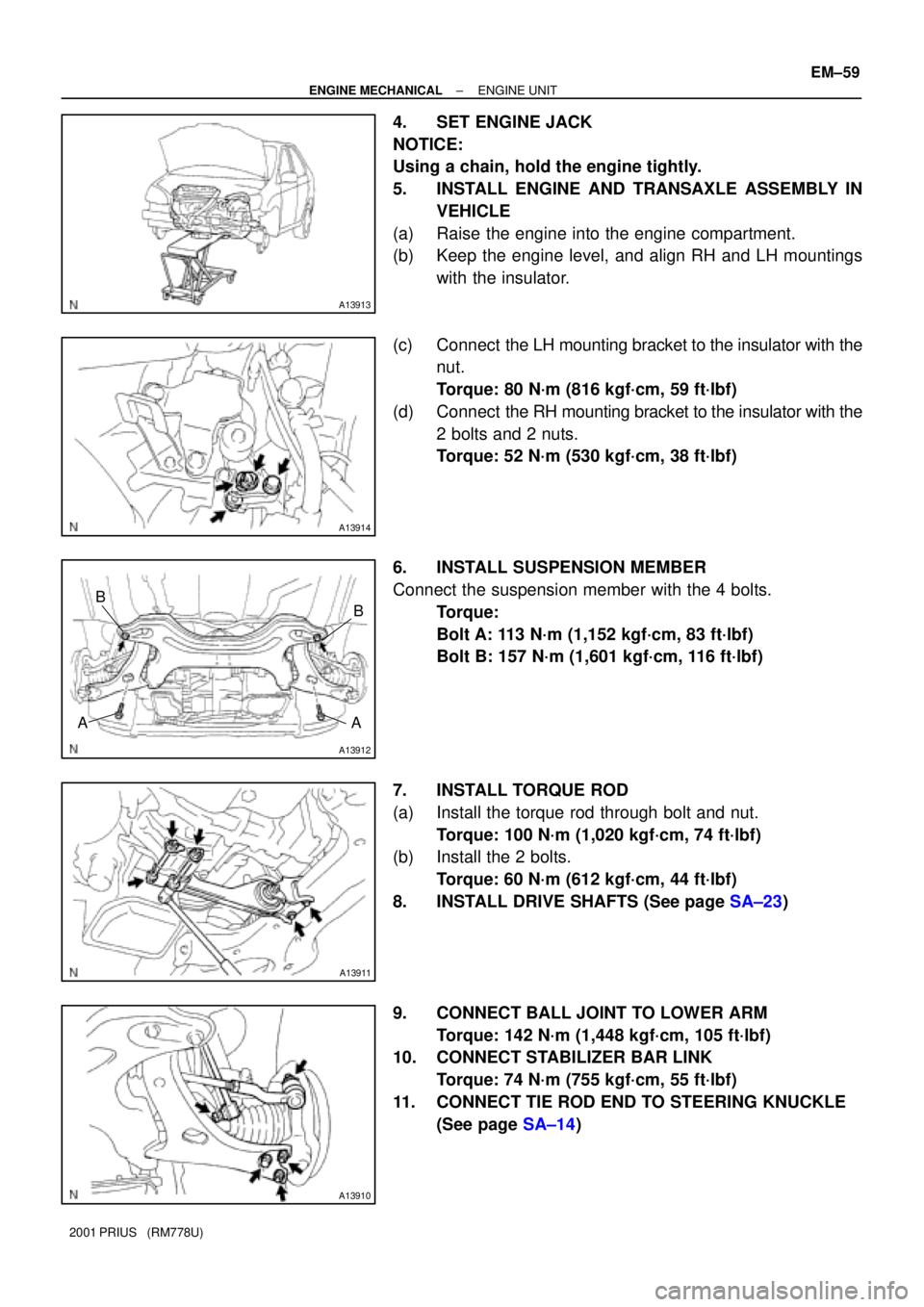
4. SET ENGINE JACK
NOTICE:
Using a chain, hold the engine tightly.
5. INSTALL ENGINE AND TRANSAXLE ASSEMBLY IN
VEHICLE
(a) Raise the engine into the engine compartment.
(b) Keep the engine level, and align RH and LH mountings
with the insulator.
(c) Connect the LH mounting bracket to the insulator with the
nut.
Torque: 80 N´m (816 kgf´cm, 59 ft´lbf)
(d) Connect the RH mounting bracket to the insulator with the
2 bolts and 2 nuts.
Torque: 52 N´m (530 kgf´cm, 38 ft´lbf)
6. INSTALL SUSPENSION MEMBER
Connect the suspension member with the 4 bolts.
Torque:
Bolt A: 113 N´m (1,152 kgf´cm, 83 ft´lbf)
Bolt B: 157 N´m (1,601 kgf´cm, 116 ft´lbf)
7. INSTALL TORQUE ROD
(a) Install the torque rod through bolt and nut.
Torque: 100 N´m (1,020 kgf´cm, 74 ft´lbf)
(b) Install the 2 bolts.
Torque: 60 N´m (612 kgf´cm, 44 ft´lbf)
8. INSTALL DRIVE SHAFTS (See page SA±23)
9. CONNECT BALL JOINT TO LOWER ARM
Torque: 142 N´m (1,448 kgf´cm, 105 ft´lbf)
10. CONNECT STABILIZER BAR LINK
Torque: 74 N´m (755 kgf´cm, 55 ft´lbf)
11. CONNECT TIE ROD END TO STEERING KNUCKLE
(See page SA±14)
Page 1654 of 1943

SA0CC±10
R03031
R15157
Front
R07928
R14731
Backlash:Deviation: SA±2
± SUSPENSION AND AXLETIRE AND WHEEL
1452 Author�: Date�:
2001 PRIUS (RM778U)
TIRE AND WHEEL
INSPECTION
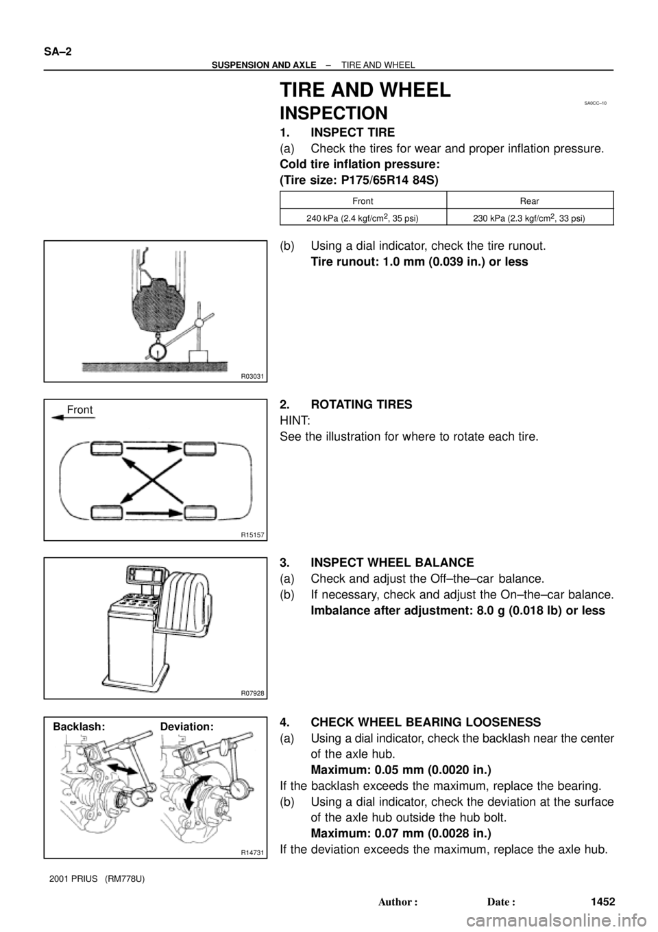
1. INSPECT TIRE
(a) Check the tires for wear and proper inflation pressure.
Cold tire inflation pressure:
(Tire size: P175/65R14 84S)
FrontRear
240 kPa (2.4 kgf/cm2, 35 psi)230 kPa (2.3 kgf/cm2, 33 psi)
(b) Using a dial indicator, check the tire runout.
Tire runout: 1.0 mm (0.039 in.) or less
2. ROTATING TIRES
HINT:
See the illustration for where to rotate each tire.
3. INSPECT WHEEL BALANCE
(a) Check and adjust the Off±the±car balance.
(b) If necessary, check and adjust the On±the±car balance.
Imbalance after adjustment: 8.0 g (0.018 lb) or less
4. CHECK WHEEL BEARING LOOSENESS
(a) Using a dial indicator, check the backlash near the center
of the axle hub.
Maximum: 0.05 mm (0.0020 in.)
If the backlash exceeds the maximum, replace the bearing.
(b) Using a dial indicator, check the deviation at the surface
of the axle hub outside the hub bolt.
Maximum: 0.07 mm (0.0028 in.)
If the deviation exceeds the maximum, replace the axle hub.