Page 1713 of 1943
F12197
SR±20
± STEERINGELECTRIC POWER STEERING GEAR
2001 PRIUS (RM778U)
(b) Remove the 4 bolts and electric power steering gear as-
sembly from the front suspension member.
(c) Remove the bracket and grommet from the electric power
steering gear assembly.
Page 1718 of 1943
SR1BO±01
F12847
Front
F12197
F15034
Serrated Part
F15035
Main Shaft Lower
Dust Seal
Body
Engine Compartment SideCab Side
± STEERINGELECTRIC POWER STEERING GEAR
SR±25
2001 PRIUS (RM778U)
INSTALLATION
1. INSTALL ELECTRIC POWER STEERING GEAR AS-
SEMBLY
(a) Install the grommet and bracket to the electric power
steering gear assembly.
HINT:
Install the bracket with the inscribed mark facing to the front of
the vehicle.
(b) Install the electric power steering gear assembly with the
4 new bolts to the front suspension member.
Torque: 83 N´m (850 kgf´cm, 61 ft´lbf)
(c) Install the stabilizer bar (See page SA±43).
(d) To prevent the main shaft lower dust seal from damaging,
wind vinyl tape on the serrated part of the control valve
shaft.
(e) Turn over the main shaft lower dust seal from the engine
compartment side to the cab.
2. INSTALL SUSPENSION MEMBER AND ELECTRIC
POWER STEERING GEAR ASSEMBLY (See page
SA±43)
3. CONNECT TORQUE ROD (See page SA±43)
Page 1719 of 1943

F12196
F12214
Matchmarks
A
B
SR±26
± STEERINGELECTRIC POWER STEERING GEAR
2001 PRIUS (RM778U)
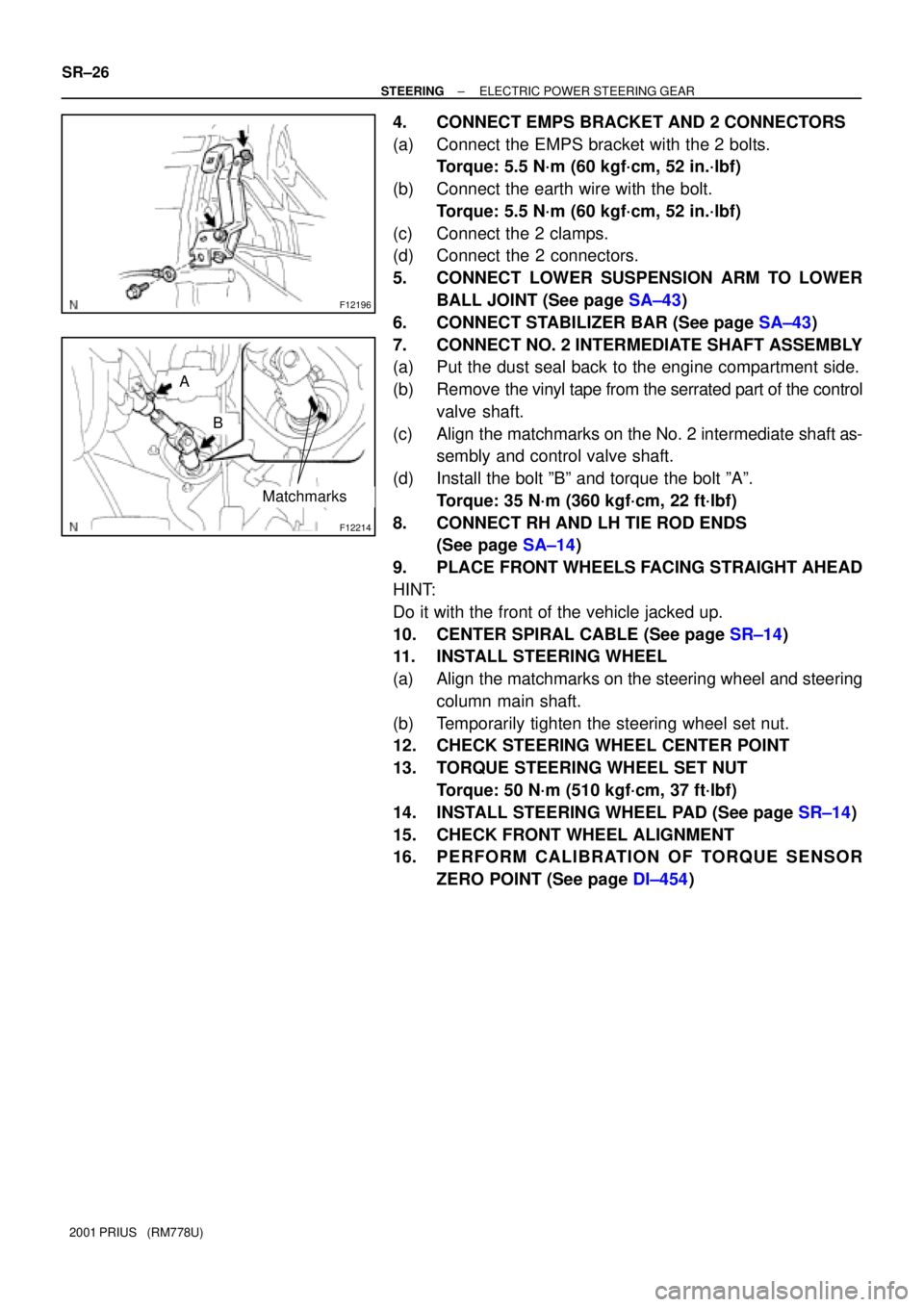
4. CONNECT EMPS BRACKET AND 2 CONNECTORS
(a) Connect the EMPS bracket with the 2 bolts.
Torque: 5.5 N´m (60 kgf´cm, 52 in.´lbf)
(b) Connect the earth wire with the bolt.
Torque: 5.5 N´m (60 kgf´cm, 52 in.´lbf)
(c) Connect the 2 clamps.
(d) Connect the 2 connectors.
5. CONNECT LOWER SUSPENSION ARM TO LOWER
BALL JOINT (See page SA±43)
6. CONNECT STABILIZER BAR (See page SA±43)
7. CONNECT NO. 2 INTERMEDIATE SHAFT ASSEMBLY
(a) Put the dust seal back to the engine compartment side.
(b) Remove the vinyl tape from the serrated part of the control
valve shaft.
(c) Align the matchmarks on the No. 2 intermediate shaft as-
sembly and control valve shaft.
(d) Install the bolt ºBº and torque the bolt ºAº.
Torque: 35 N´m (360 kgf´cm, 22 ft´lbf)
8. CONNECT RH AND LH TIE ROD ENDS
(See page SA±14)
9. PLACE FRONT WHEELS FACING STRAIGHT AHEAD
HINT:
Do it with the front of the vehicle jacked up.
10. CENTER SPIRAL CABLE (See page SR±14)
11. INSTALL STEERING WHEEL
(a) Align the matchmarks on the steering wheel and steering
column main shaft.
(b) Temporarily tighten the steering wheel set nut.
12. CHECK STEERING WHEEL CENTER POINT
13. TORQUE STEERING WHEEL SET NUT
Torque: 50 N´m (510 kgf´cm, 37 ft´lbf)
14. INSTALL STEERING WHEEL PAD (See page SR±14)
15. CHECK FRONT WHEEL ALIGNMENT
16. PERFORM CALIBRATION OF TORQUE SENSOR
ZERO POINT (See page DI±454)