Page 1882 of 1943
H15447
Defroster Nozzle
J
J
JJ
J
J
J
No. 2 Side Defroster Nozzle
No. 2 Side
Defroster Nozzle
No. 1 Heater to Register Duct
No. 2 Instrument Panel
Cushion
No. 3 Instrument
Panel Cushion
No. 4 Instrument
Panel Cushion Navigation Antenna
J
J
J
JJ
J
No. 1 Instrument Panel
CushionM
No. 1 Pin
M
No. 1 Pin
J
Center
Bracket Fuse Box Opening Cover
Instrument Panel Wire
No. 1 Safty Pad
No. 2 Safty PadM
M
MM
MMM
M
M
M
MM
M
BO±60
± BODYINSTRUMENT PANEL
1845 Author�: Date�:
2001 PRIUS (RM778U)
Page 1919 of 1943
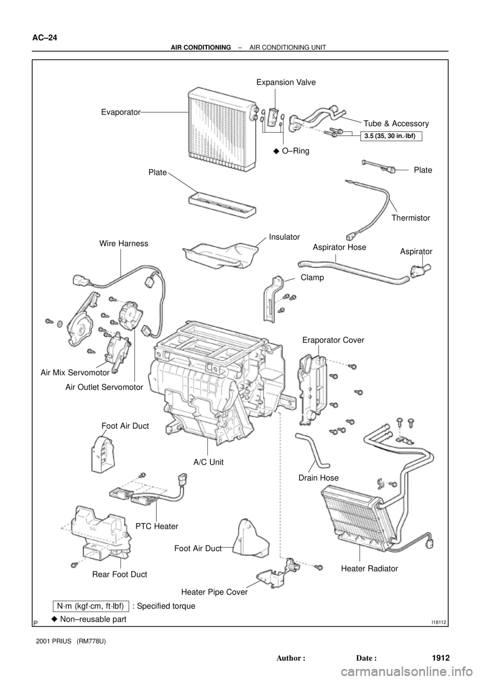
I18112
N´m (kgf´cm, ft´lbf) : Specified torque
�Non±reusable partEvaporatorExpansion Valve
Tube & Accessory
Plate
Thermistor
Aspirator
Eraporator CoverAspirator Hose
Clamp Insulator Plate
Wire Harness
Air Mix Servomotor
Air Outlet Servomotor
Foot Air Duct
PTC HeaterA/C Unit
Foot Air Duct
Heater Pipe CoverDrain Hose
Heater Radiator
Rear Foot DuctO±Ring
3.5 (35, 30 in.´lbf)
�
AC±24
± AIR CONDITIONINGAIR CONDITIONING UNIT
1912 Author�: Date�:
2001 PRIUS (RM778U)
Page 1921 of 1943

I06919
Disconnect the tube
using hand
Screw
Driver
Tube
I17982
I18108
View
Upper
Lower RH LH
MarkingHose Clip
A
View
Second RidgeA
Upper
Lower
20°
20°
I17984
I17985
AC±26
± AIR CONDITIONINGAIR CONDITIONING UNIT
2001 PRIUS (RM778U)
NOTICE:
�Do not use tools like screwdriver to remove the tube.
�Cap the open fittings immediately to keep moisture or
dirt out of the system.
HINT:
At the time of reassembly, please refer to the following item.
Lubricate 4 new O±rings with compressor oil and install them
to the valve.
5. DISCONNECT WATER HOSES FROM HEATER RA-
DIATOR PIPES
(a) Using pliers, grip the claw of the hose clip and slide the
hose clip along the hose.
(b) Disconnect the heater hoses.
HINT:
At the time of installation, please refer to the following item.
Push the water hose onto the heater radiator pipe as far as se-
cond ridge on the pipe and install the hose clip.
6. REMOVE INSTRUMENT PANEL AND REINFORCE-
MENT (See page BO±62)
7. REMOVE BLOWER UNIT (See page AC±32)
8. REMOVE A/C UNIT
(a) Remove the 2 screws and defroster duct.
(b) Remove the foot air duct.
(c) Disconnect the connectors.
(d) Remove the 2 nuts and A/C unit.
Page 1928 of 1943

I18027
Heater Main Relay
Magnetic
Clutch
Relay
Cooling
Fan No. 3
Relay
Cooling
Fan No. 1
Relay
Cooling
Fan No. 2
Relay
AC36O±01
I18028Heater 2 Relay
Heater 1 Relay
Heater 3 Relay
Water
Pump
Relay
I18286
3
2
15 4
1 4
32
5
N23635
3
2
15
4
Z18060
13
2 5
5 2
3
1
± AIR CONDITIONINGRELAY
AC±65
1953 Author�: Date�:
2001 PRIUS (RM778U)
RELAY
INSPECTION
1. REMOVE RELAY
(a) Remove the relay from the engine room J/B.
(b) Remove the relay from the engine room R/B No. 3.
2. INSPECT HEATER MAIN RELAY CONTINUITY
ConditionTester connectionSpecified condition
Constant3 ± 5
2 ± 4Continuity
Apply B+ between
terminals 5 and 3.1 ± 2Continuity
If continuity is not as specified, replace the relay.
3. INSPECT COOLING FAN NO. 2 RELAY CONTINUITY
ConditionTester connectionSpecified condition
Constant1 ± 2
3 ± 4Continuity
Apply B+ between
terminals 1 and 2.3 ± 5Continuity
If continuity is not as specified, replace the relay.
4. INSPECT MAGNETIC CLUTCH, COOLING FAN NO. 1,
3, HEATER 1, 2, WATER PUMP RELAY CONTINUITY
ConditionTester connectionSpecified condition
Constant1 ± 2Continuity
Apply B+ between
terminals 1 and 2.3 ± 5Continuity
If continuity is not as specified, replace the relay.
Page 1929 of 1943
I07286
1
2 3
51
2
3
5 AC±66
± AIR CONDITIONINGRELAY
1954 Author�: Date�:
2001 PRIUS (RM778U)
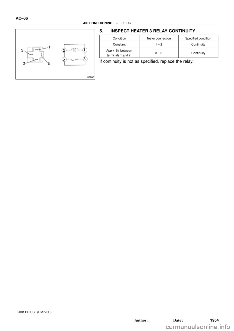
5. INSPECT HEATER 3 RELAY CONTINUITY
ConditionTester connectionSpecified condition
Constant1 ± 2Continuity
Apply B+ between
terminals 1 and 2.3 ± 5Continuity
If continuity is not as specified, replace the relay.
Page 1932 of 1943
AC36J±01
I17991
I18015
I18034
I18035
I18036 : Bulb
AC±76
± AIR CONDITIONINGHEATER CONTROL ASSEMBLY
2001 PRIUS (RM778U)
DISASSEMBLY
1. REMOVE CONTROL KNOBS
(a) Pull out the 5 control knobs.
(b) Remove the 3 nuts.
2. REMOVE MULTI DISPLAY & RADIO RECEIVER AS-
SEMBLY
Remove the 4 screws and multi display & radio receiver assem-
bly.
3. REMOVE A/C AMPLIFIER
(a) Remove the 12 screws and cover.
(b) Unlock the connector lock and pull out the flat harness
from center cluster module.
4. REMOVE BULBS
Using a screwdriver, turn the bulb to the left and pull out the
bulb.
Page 1933 of 1943
I18037
± AIR CONDITIONINGHEATER CONTROL ASSEMBLY
AC±77
2001 PRIUS (RM778U)
5. REMOVE CLUSTER MODULE CIRCUIT
Remove the 6 screws and center cluster module.
Page 1934 of 1943
AC36K±01
I18038 : Bulb
5
10
I07872
I17978
1
7
AC±78
± AIR CONDITIONINGHEATER CONTROL ASSEMBLY
2001 PRIUS (RM778U)
INSPECTION
1. INSPECT ILLUMINATION OPERATION
(a) Connect the positive (+) lead from the battery to terminal
5 and negative (±) lead to terminal 10, then check that the
illumination lights up.
If operation is not as specified, check the faulty bulb.
(b) Apply the tester as shown in the illustration to the test for
continuity.
If continuity exists, replace the heater control.
If no continuity exists, replace the bulb.
2. INSPECT INDICATOR OPERATION
Connect the positive (+) lead from the battery to terminal 1 and
negative (±) lead to terminal 7, then check that the illumination
light up.
If operation is not as specified, proceed next inspection.


DISASSEMBLY
1. REMOVE CONTROL KNOBS
(a) Pull out the 5 control knobs.
(b")

5. REMOVE CLUSTER MODULE CIRCUIT
Remove the 6 screws and center cluster module.")

INSPECTION
1. INSPECT ILLUMINATION OPERATION
(a) Connect the positive (+) le")