Page 1435 of 1943
DI±928
± DIAGNOSTICSAIR CONDITIONING SYSTEM
2001 PRIUS (RM778U)
3 Check harness and connector between heater main relay and body ground, heat-
er main relay and body ECU (See page IN±41).
NG Check and replace harness and connector.
OK
Check multiplex communication system (See page DI±750).
Page 1449 of 1943
DI±942
± DIAGNOSTICSAIR CONDITIONING SYSTEM
2001 PRIUS (RM778U)
PTC Heater Circuit (Quick Heater)
CIRCUIT DESCRIPTION
A/C amplifier switches the HTR3 relay ON by signal from the A/C amplifier. It supplies power to PTC heater
(Quick heater).
DI7SP±01
Page 1450 of 1943
I18386
A8 A8 13
6HTR2
HTR0 A/C Amplifier
P P
IE118
IE116 L±R
P±B
P±B
P±B
L±Y
G±R
1
23
41
2 P2
P2P2
P2P1
P1PTC Heater
W±B
W±B W±B
W±B
W±B
J11
J/CJ1
J/C AA
AA
IE ID IA1
IA1 Engine Room R/B No.3
3
3
3
3
3
3 3
3
3
3
3
3
3
3
3
3HTR3 Relay
HTR2 Relay
HTR1 Relay1
2
5
3
1
2
5
3
1
2
5
3
HTR1
HTR2
HTR3 R±L
G
R±L
G±W
R±L
B±R
W
Instrument Panel J/B
2G
2D
2H
2K 2B8
6
1
8 3GAUGE
IG1 Relay
5 3
21
AM1
B±Y
W±G
24
AM1 IG1 I15
Ignition SW
DC/DCF13
F13 F131
1 1FL Block No.1
F18 FL Block No.2
BatteryMAINW±B
W5
1
± DIAGNOSTICSAIR CONDITIONING SYSTEM
DI±943
2001 PRIUS (RM778U)
WIRING DIAGRAM
Page 1453 of 1943
I18393
DI±946
± DIAGNOSTICSAIR CONDITIONING SYSTEM
2001 PRIUS (RM778U)
5 Check harness and connector between A/C amplifier and HTR1 and HTR2 fuses
(See page IN±41).
NG Check and replace harness and connector.
OK
Check and replace A/C amplifier.
6 Check PTC heater.
PREPARATION:
Remove the heater radiator (See page AC±51).
CHECK:
Check continuity between terminals of PTC heater connector,
as shown in the chart.
OK:
Tester connectionResult
1 ± 2Continuity
3 ± 4Continuity
NG Replace heater radiator.
OK
Check harness and connector between PTC heater and HTR1, HT2 relays, PTC heater and body
ground (See page IN±41).
Page 1454 of 1943
± DIAGNOSTICSAIR CONDITIONING SYSTEM
DI±947
2001 PRIUS (RM778U)
PTC Heater Circuit (Heater Radiator)
CIRCUIT DESCRIPTION
A/C amplifier switches the HTR1 relay and HTR2 relay ON by signal from the A/C amplifier. It supplies power
to PTC heater (Heater radiator).
DI7SQ±01
Page 1455 of 1943
I18386
A8 A8 13
6HTR2
HTR0 A/C Amplifier
P P
IE118
IE116 L±R
P±B
P±B
P±B
L±Y
G±R
1
23
41
2 P2
P2P2
P2P1
P1PTC Heater
W±B
W±B W±B
W±B
W±B
J11
J/CJ1
J/C AA
AA
IE ID IA1
IA1 Engine Room R/B No.3
3
3
3
3
3
3 3
3
3
3
3
3
3
3
3
3HTR3 Relay
HTR2 Relay
HTR1 Relay1
2
5
3
1
2
5
3
1
2
5
3
HTR1
HTR2
HTR3 R±L
G
R±L
G±W
R±L
B±R
W
Instrument Panel J/B
2G
2D
2H
2K 2B8
6
1
8 3GAUGE
IG1 Relay
5 3
21
AM1
B±Y
W±G
24
AM1 IG1 I15
Ignition SW
DC/DCF13
F13 F131
1 1FL Block No.1
F18 FL Block No.2
BatteryMAINW±B
W5
1 DI±948
± DIAGNOSTICSAIR CONDITIONING SYSTEM
2001 PRIUS (RM778U)
WIRING DIAGRAM
Page 1458 of 1943
I18395
± DIAGNOSTICSAIR CONDITIONING SYSTEM
DI±951
2001 PRIUS (RM778U)
5 Check harness and connector between A/C amplifier and HTR3 fuse (See page
IN±41).
NG Check and replace harness and connector.
OK
Check and replace A/C amplifier.
6 Check PTC heater (Heater Radiator).
PREPARATION:
Remove the heater radiator (See page AC±27).
CHECK:
Check continuity between terminals of PTC heater connector.
OK:
Continuity exists.
NG Replace heater radiator.
OK
Check harness and connector between PTC heater and HTR3 relay, PTC heater and body ground
(See page IN±41).
Page 1490 of 1943

A12943
1
2973
4
3
368
5
A11228
1
23
45
67
8
9
10
A12944
± ENGINE MECHANICALCYLINDER HEAD
EM±31
2001 PRIUS (RM778U)
�Do not disassembly the valve timing controller as-
sembly.
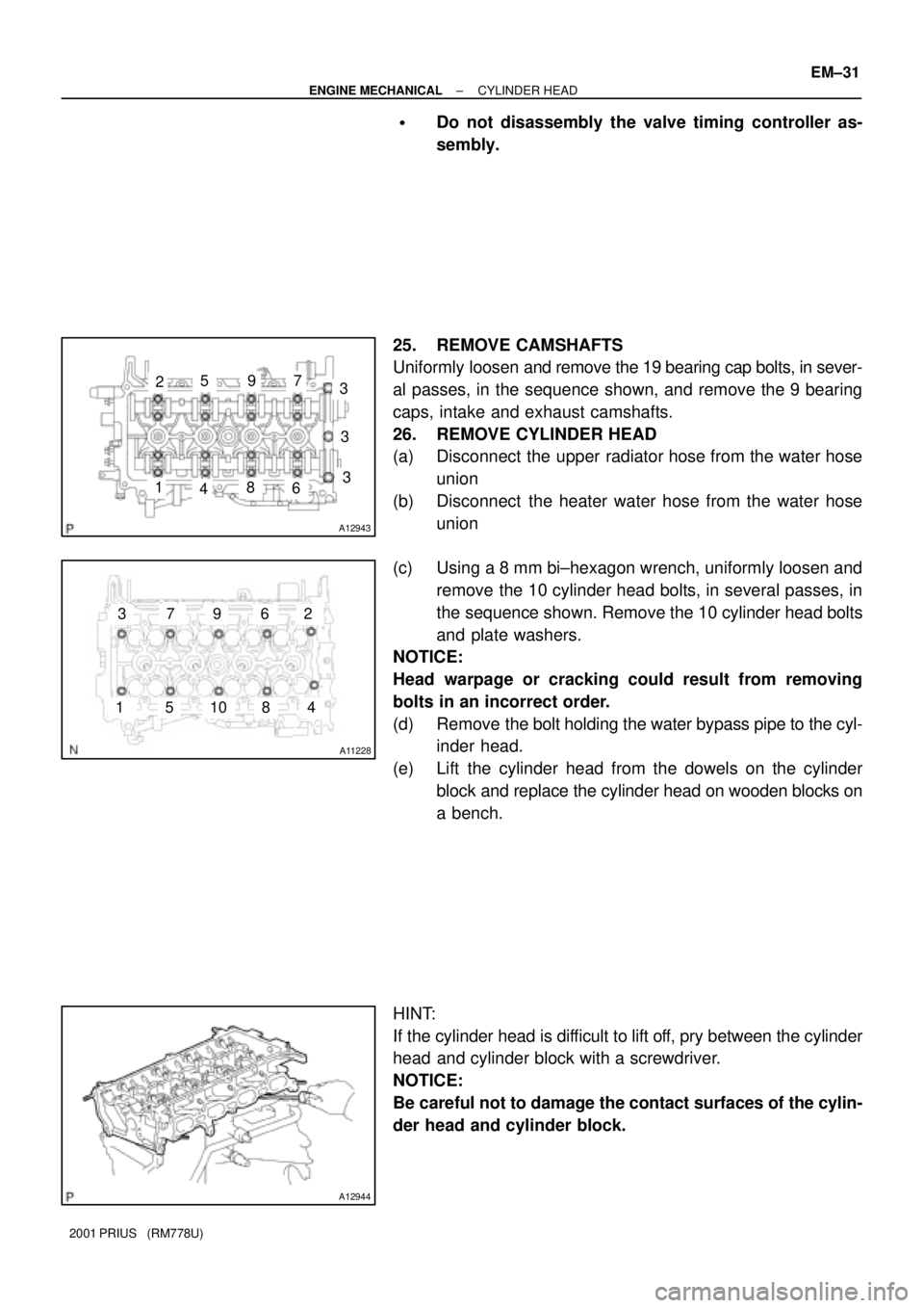
25. REMOVE CAMSHAFTS
Uniformly loosen and remove the 19 bearing cap bolts, in sever-
al passes, in the sequence shown, and remove the 9 bearing
caps, intake and exhaust camshafts.
26. REMOVE CYLINDER HEAD
(a) Disconnect the upper radiator hose from the water hose
union
(b) Disconnect the heater water hose from the water hose
union
(c) Using a 8 mm bi±hexagon wrench, uniformly loosen and
remove the 10 cylinder head bolts, in several passes, in
the sequence shown. Remove the 10 cylinder head bolts
and plate washers.
NOTICE:
Head warpage or cracking could result from removing
bolts in an incorrect order.
(d) Remove the bolt holding the water bypass pipe to the cyl-
inder head.
(e) Lift the cylinder head from the dowels on the cylinder
block and replace the cylinder head on wooden blocks on
a bench.
HINT:
If the cylinder head is difficult to lift off, pry between the cylinder
head and cylinder block with a screwdriver.
NOTICE:
Be careful not to damage the contact surfaces of the cylin-
der head and cylinder block.