Page 1504 of 1943
A12945
No.1 Cam Lobe
A12946
A12943
9
9
96
5
2
1
4
3
8
7 EM±46
± ENGINE MECHANICALCYLINDER HEAD
2001 PRIUS (RM778U)
(g) Connect the upper radiator hose to the water hose
unions.
(h) Connect the heater hose to the water hose unions.
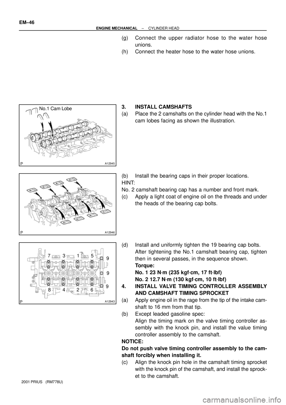
3. INSTALL CAMSHAFTS
(a) Place the 2 camshafts on the cylinder head with the No.1
cam lobes facing as shown the illustration.
(b) Install the bearing caps in their proper locations.
HINT:
No. 2 camshaft bearing cap has a number and front mark.
(c) Apply a light coat of engine oil on the threads and under
the heads of the bearing cap bolts.
(d) Install and uniformly tighten the 19 bearing cap bolts.
After tightening the No.1 camshaft bearing cap, tighten
then in several passes, in the sequence shown.
Torque:
No. 1 23 N´m (235 kgf´cm, 17 ft´lbf)
No. 2 12.7 N´m (130 kgf´cm, 10 ft´lbf)
4. INSTALL VALVE TIMING CONTROLLER ASSEMBLY
AND CAMSHAFT TIMING SPROCKET
(a) Apply engine oil in the rage from the tip of the intake cam-
shaft to 16 mm from that tip.
(b) Except leaded gasoline spec:
Align the timing mark on the valve timing controller as-
sembly with the knock pin, and install the value timing
controller assembly to the camshaft.
NOTICE:
Do not push valve timing controller assembly to the cam-
shaft forcibly when installing it.
(c) Align the knock pin hole in the camshaft timing sprocket
with the knock pin of the camshaft, and install the sprock-
et to the camshaft.
Page 1511 of 1943
EM1J0±02
A13907
A13943
± ENGINE MECHANICALENGINE UNIT
EM±53
2001 PRIUS (RM778U)
REMOVAL
1. DISCONNECT BATTERY NEGATIVE (±) TERMINAL
AND HV BATTERY SERVICE PLUG
(See page HV±1)
2. REMOVE OUTER FRONT COWL TOP PANEL AS-
SEMBLY (See page BO±32)
3. DRAIN HV COOLANT (See page HT±8)
4. DRAIN ENGINE COOLANT
5. REMOVE CONVERTER AND INVERTER ASSEMBLY
(See page HV±18)
6. REMOVE HEATER UNIT WATER PUMP
(See page AC±55)
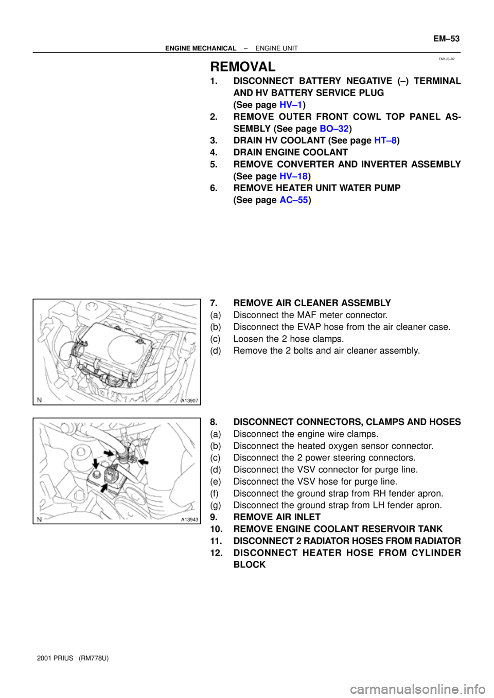
7. REMOVE AIR CLEANER ASSEMBLY
(a) Disconnect the MAF meter connector.
(b) Disconnect the EVAP hose from the air cleaner case.
(c) Loosen the 2 hose clamps.
(d) Remove the 2 bolts and air cleaner assembly.
8. DISCONNECT CONNECTORS, CLAMPS AND HOSES
(a) Disconnect the engine wire clamps.
(b) Disconnect the heated oxygen sensor connector.
(c) Disconnect the 2 power steering connectors.
(d) Disconnect the VSV connector for purge line.
(e) Disconnect the VSV hose for purge line.
(f) Disconnect the ground strap from RH fender apron.
(g) Disconnect the ground strap from LH fender apron.
9. REMOVE AIR INLET
10. REMOVE ENGINE COOLANT RESERVOIR TANK
11. DISCONNECT 2 RADIATOR HOSES FROM RADIATOR
12. DISCONNECT HEATER HOSE FROM CYLINDER
BLOCK
Page 1517 of 1943
A13939
I18009
A13909
A13938
EM±60
± ENGINE MECHANICALENGINE UNIT
2001 PRIUS (RM778U)
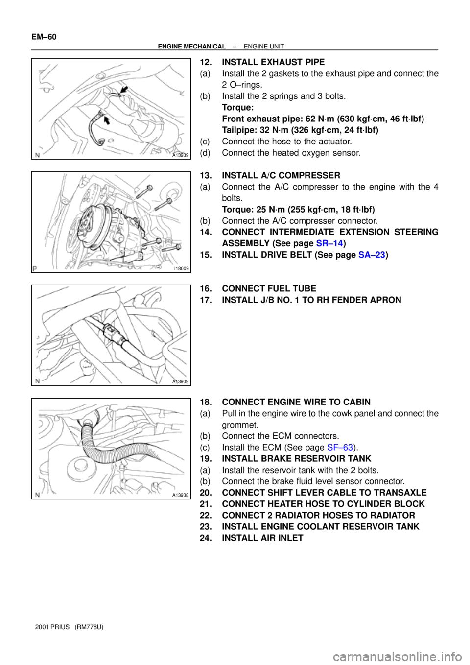
12. INSTALL EXHAUST PIPE
(a) Install the 2 gaskets to the exhaust pipe and connect the
2 O±rings.
(b) Install the 2 springs and 3 bolts.
Torque:
Front exhaust pipe: 62 N´m (630 kgf´cm, 46 ft´lbf)
Tailpipe: 32 N´m (326 kgf´cm, 24 ft´lbf)
(c) Connect the hose to the actuator.
(d) Connect the heated oxygen sensor.
13. INSTALL A/C COMPRESSER
(a) Connect the A/C compresser to the engine with the 4
bolts.
Torque: 25 N´m (255 kgf´cm, 18 ft´lbf)
(b) Connect the A/C compresser connector.
14. CONNECT INTERMEDIATE EXTENSION STEERING
ASSEMBLY (See page SR±14)
15. INSTALL DRIVE BELT (See page SA±23)
16. CONNECT FUEL TUBE
17. INSTALL J/B NO. 1 TO RH FENDER APRON
18. CONNECT ENGINE WIRE TO CABIN
(a) Pull in the engine wire to the cowk panel and connect the
grommet.
(b) Connect the ECM connectors.
(c) Install the ECM (See page SF±63).
19. INSTALL BRAKE RESERVOIR TANK
(a) Install the reservoir tank with the 2 bolts.
(b) Connect the brake fluid level sensor connector.
20. CONNECT SHIFT LEVER CABLE TO TRANSAXLE
21. CONNECT HEATER HOSE TO CYLINDER BLOCK
22. CONNECT 2 RADIATOR HOSES TO RADIATOR
23. INSTALL ENGINE COOLANT RESERVOIR TANK
24. INSTALL AIR INLET
Page 1518 of 1943
A13943
A13907
± ENGINE MECHANICALENGINE UNIT
EM±61
2001 PRIUS (RM778U)
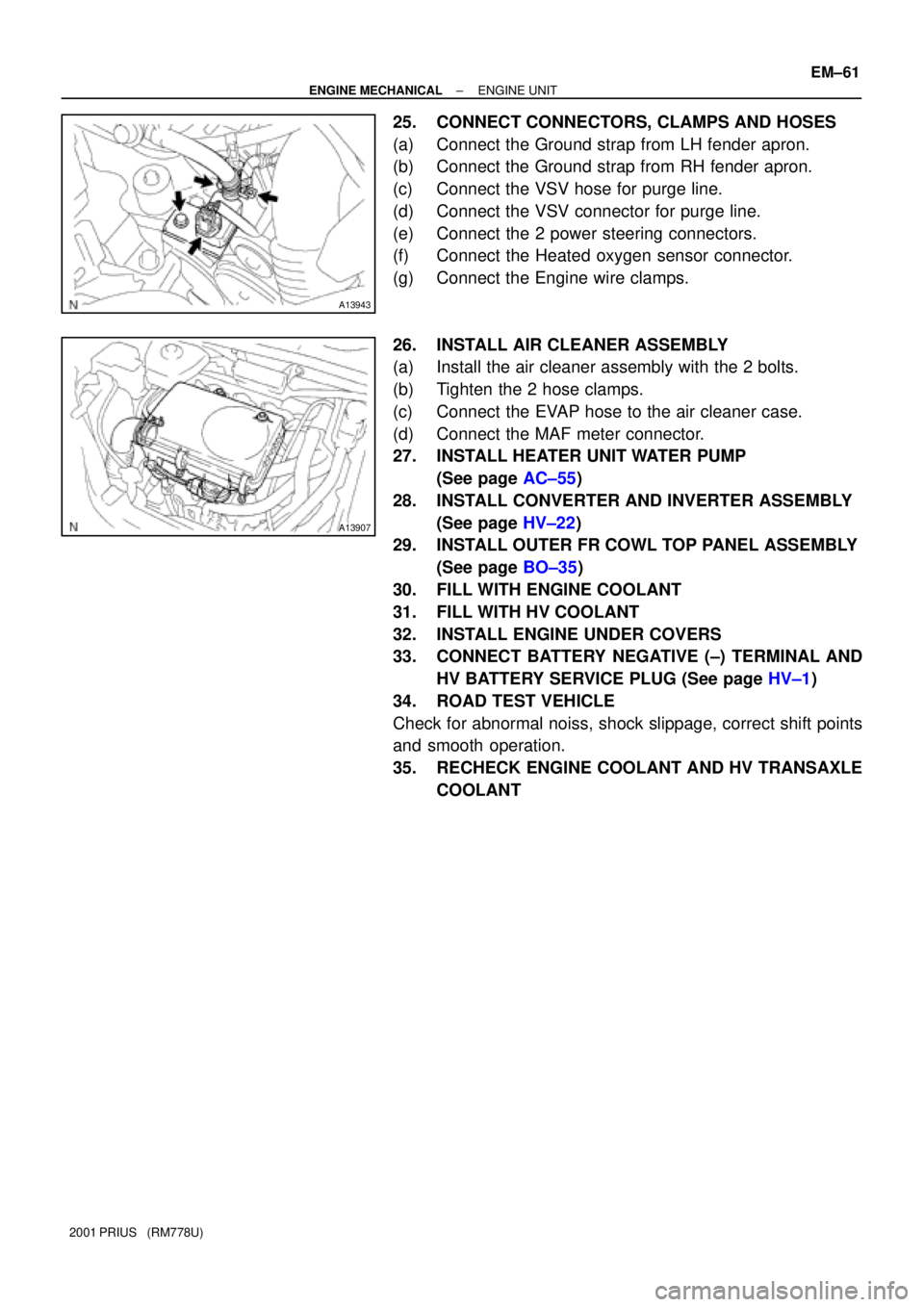
25. CONNECT CONNECTORS, CLAMPS AND HOSES
(a) Connect the Ground strap from LH fender apron.
(b) Connect the Ground strap from RH fender apron.
(c) Connect the VSV hose for purge line.
(d) Connect the VSV connector for purge line.
(e) Connect the 2 power steering connectors.
(f) Connect the Heated oxygen sensor connector.
(g) Connect the Engine wire clamps.
26. INSTALL AIR CLEANER ASSEMBLY
(a) Install the air cleaner assembly with the 2 bolts.
(b) Tighten the 2 hose clamps.
(c) Connect the EVAP hose to the air cleaner case.
(d) Connect the MAF meter connector.
27. INSTALL HEATER UNIT WATER PUMP
(See page AC±55)
28. INSTALL CONVERTER AND INVERTER ASSEMBLY
(See page HV±22)
29. INSTALL OUTER FR COWL TOP PANEL ASSEMBLY
(See page BO±35)
30. FILL WITH ENGINE COOLANT
31. FILL WITH HV COOLANT
32. INSTALL ENGINE UNDER COVERS
33. CONNECT BATTERY NEGATIVE (±) TERMINAL AND
HV BATTERY SERVICE PLUG (See page HV±1)
34. ROAD TEST VEHICLE
Check for abnormal noiss, shock slippage, correct shift points
and smooth operation.
35. RECHECK ENGINE COOLANT AND HV TRANSAXLE
COOLANT
Page 1573 of 1943
± COOLINGCOOLANT
CO±3
2001 PRIUS (RM778U)
(f) Remove the radiator cap and check the engine coolant
level of the radiator. If it has dropped, repeat steps (d) to
(g).
(g) Bleed air from water pump.
Set the vehicle in the following conditions:
�Ignition switch ON
�Blower speed control dial to LO
�Temperature control dial to MAX. HOT
(h) Operate the water pump in the following conditions:
�The engine stopped
�The blower switch ON
�Temperature control dial at MAX. HOT
HINT:
Operate the water pump until a sound of the air±containing en-
gine coolant can not be heard from the heater core.
(i) When the engine coolant remains full, fill the radiator res-
ervoir tank with engine coolant to the maximum level.
3. CHECK FOR COOLANT LEAKS
4. CHECK ENGINE COOLANT SPECIFIC GRAVITY IS
CORRECT
Page 1575 of 1943
B11773
Radiator Cap Tester
± COOLINGRADIATOR AND CONDENSER MODULE
CO±15
2001 PRIUS (RM778U)
3. INSPECT COOLING SYSTEM FOR LEAKS
(a) Fill the radiator with coolant and attach a radiator cap tes-
ter.
(b) Warm up the engine.
(c) Pump it to 118 kPa (1.2 kgf´cm
2, 17.1 psi), and check that
the pressure drops.
If the pressure drops, check the hoses, radiator or water pump
for leaks. If no external leaks are found, check the heater core,
cylinder block and head.
4. REINSTALL RADIATOR CAP
Page 1602 of 1943
B12009
± HYBRID VEHICLE CONTROLCONVERTER AND INVERTER ASSEMBLY
HV±15
1345 Author�: Date�:
2001 PRIUS (RM778U)
2. INSPECT CONVERTER
(a) Function check
Measure the voltage of an auxiliary battery terminal when
the ºREADYº lamp is OFF and ON.
READY lamp is OFF: Approx. 12 V
READY lamp is ON: Approx. 14 V
(b) Output current check
(1) Disconnect the MG2 power cable from the inverter
(See page HV±18).
(2) Install AC/DC 400 A probe to the wire harness of the
IP connector of the converter.
(3) Connect the MG2 power cable to the inverter (See
page HV±22).
(4) With the READY lamp ON, operate electric devices
one by one and measure the output current.
Standard: 100 A or less
HINT:
If more than 100 A is shown momentarily, check for the follow-
ings.
�Ground short of electric device.
�Overload caused by installation of excessive device.
�PTC heater operation.
Page 1765 of 1943
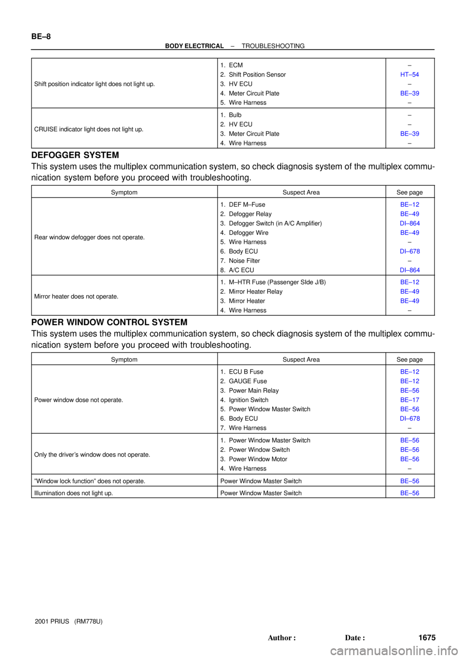
BE±8
± BODY ELECTRICALTROUBLESHOOTING
1675 Author�: Date�:
2001 PRIUS (RM778U) Shift position indicator light does not light up.
1. ECM
2. Shift Position Sensor
3. HV ECU
4. Meter Circuit Plate
5. Wire Harness±
HT±54
±
BE±39
±
CRUISE indicator light does not light up.
1. Bulb
2. HV ECU
3. Meter Circuit Plate
4. Wire Harness±
±
BE±39
±
DEFOGGER SYSTEM
This system uses the multiplex communication system, so check diagnosis system of the multiplex commu-
nication system before you proceed with troubleshooting.
SymptomSuspect AreaSee page
Rear window defogger does not operate.
1. DEF M±Fuse
2. Defogger Relay
3. Defogger Switch (in A/C Amplifier)
4. Defogger Wire
5. Wire Harness
6. Body ECU
7. Noise Filter
8. A/C ECUBE±12
BE±49
DI±864
BE±49
±
DI±678
±
DI±864
Mirror heater does not operate.
1. M±HTR Fuse (Passenger SIde J/B)
2. Mirror Heater Relay
3. Mirror Heater
4. Wire HarnessBE±12
BE±49
BE±49
±
POWER WINDOW CONTROL SYSTEM
This system uses the multiplex communication system, so check diagnosis system of the multiplex commu-
nication system before you proceed with troubleshooting.
SymptomSuspect AreaSee page
Power window dose not operate.
1. ECU B Fuse
2. GAUGE Fuse
3. Power Main Relay
4. Ignition Switch
5. Power Window Master Switch
6. Body ECU
7. Wire HarnessBE±12
BE±12
BE±56
BE±17
BE±56
DI±678
±
Only the driver's window does not operate.
1. Power Window Master Switch
2. Power Window Switch
3. Power Window Motor
4. Wire HarnessBE±56
BE±56
BE±56
±
ºWindow lock functionº does not operate.Power Window Master SwitchBE±56
Illumination does not light up.Power Window Master SwitchBE±56