Page 1223 of 1943
± DIAGNOSTICSCOMBINATION METER SYSTEM
DI±675
2001 PRIUS (RM778U) Trip meter cannot be reset.
1. ODO/TRIP switch
2. Combination meter ECU
Display cannot be shifted among ODO, TRIPA and TRIPB.1. ODO/TRIP switch
2. Combination meter ECU
Without resetting, the display returns to 0.0 km.1. ODO/TRIP switch
2. +B wire harness
3. Combination meter ECU
Error of accumulated distance is large.1. Accessory that utilizes vehicle speed signals.
2. GND wire harness
3. Brake ECU
4. Wire harness and connector
5. Combination meter ECU
Others:
SymptomSuspect area
Some indicators or warning lights are always ON.1. Meter circuit plate
2. Corresponding switch and ECU
3. Combination meter ECU
4. Multiplex communication circuit
Some indicators or warning lights do not light up.1. Bulb
2. Meter circuit plate
3. Corresponding switch and ECU
4. Combination meter ECU
5. Multiplex communication circuit
Buzzer does not stop.1. Combination meter ECU
2. Corresponding switch and ECU
Page 1224 of 1943
± DIAGNOSTICSCOMBINATION METER SYSTEM
DI±681
2001 PRIUS (RM778U)
5. Indicators or warning lights do not light up. (*multiplex communication circuit input
indicator or warning)
INSPECTION PROCEDURE
1 Multiplex communication circuit input indicator or warning.
2 Communication check.
CHECK:
Check if the communication between the combination meter and the multiplex communication circuit is nor-
mal or not.
Ye s
No Communication error. Wire harness faulty.
3 Check the bulb or circuit plate.
CHECK:
Check if the bulb circuit plate is normal or not. Check open or short circuit in wire harness.
Ye s
No Bulb or circuit plate faulty.
DI7XX±01
Page 1236 of 1943

I15485
BatteryB9
BODY ECU
11
F112 5
6 3
2 15
1
11
1 WID2 2F
2K 2HTAIL
RELAY7.5A
TAIL Instrument Panel J/Bto Taillight
F18
FL BLock No. 2 FL Block No. 1LG LG
F13B±GTRLY
100A DC/DC 120A MAIN DI±696
± DIAGNOSTICSBODY CONTROL SYSTEM
2001 PRIUS (RM778U)
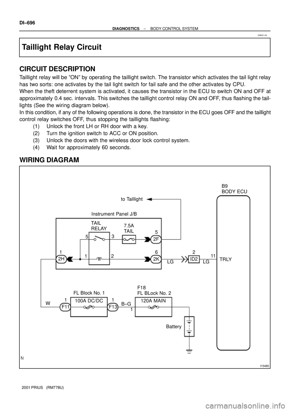
Taillight Relay Circuit
CIRCUIT DESCRIPTION
Taillight relay will be ºONº by operating the taillight switch. The transistor which activates the tail light relay
has two sorts: one activates by the tail light switch for fail safe and the other activates by CPU.
When the theft deterrent system is activated, it causes the transistor in the ECU to switch ON and OFF at
approximately 0.4 sec. intervals. This switches the taillight control relay ON and OFF, thus flashing the tail-
lights (See the wiring diagram below).
In this condition, if any of the following operations is done, the transistor in the ECU goes OFF and the taillight
control relay switches OFF, thus stopping the taillights flashing:
(1) Unlock the front LH or RH door with a key.
(2) Turn the ignition switch to ACC or ON position.
(3) Unlock the doors with the wireless door lock control system.
(4) Wait for approximately 60 seconds.
WIRING DIAGRAM
DI6QY±04
Page 1238 of 1943

I15484
2 3 66
8 7
1 4 2
1
4
3 2 1 1
11
1
710
883
A L D
FE
E
E
LE
ER±L
R±G
R±W
R±G R±W R±W R±W
R±G
R±G B±G
R±G B
F13 F12
2I
2A 1B1F
1F
1F3
ID2 IA2J20
J/C
IA1
J4J5
ID 2K 2A
15
17
BatteryC10 High Beam
Indicator Light
(Comb. meter) F18
FL Block No. 2
J11
J/CJ4 H2
Headlight RH
10A HEAD (LH) 10A HEAD (RH)
Short Pin HEAD RelayEngine Room J/BB9
Body ECU
Short Pin
120A MAIN
Instrument
Panel J/BJ12 J13
W±B
H1
Headlight
LH
1
FL Block No. 13
1
HRLY
Instrument
Panel J/B DI±698
± DIAGNOSTICSBODY CONTROL SYSTEM
2001 PRIUS (RM778U)
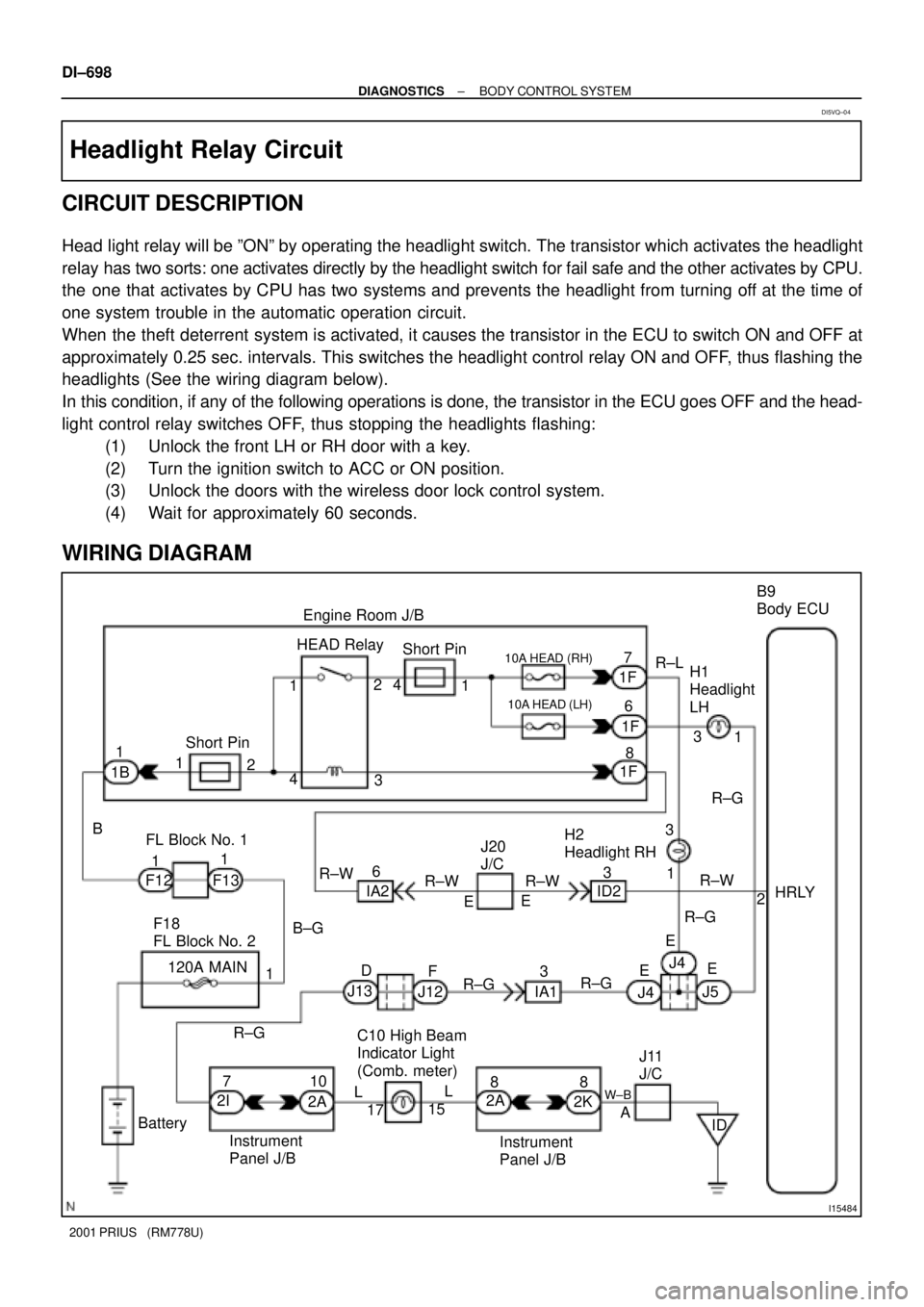
Headlight Relay Circuit
CIRCUIT DESCRIPTION
Head light relay will be ºONº by operating the headlight switch. The transistor which activates the headlight
relay has two sorts: one activates directly by the headlight switch for fail safe and the other activates by CPU.
the one that activates by CPU has two systems and prevents the headlight from turning off at the time of
one system trouble in the automatic operation circuit.
When the theft deterrent system is activated, it causes the transistor in the ECU to switch ON and OFF at
approximately 0.25 sec. intervals. This switches the headlight control relay ON and OFF, thus flashing the
headlights (See the wiring diagram below).
In this condition, if any of the following operations is done, the transistor in the ECU goes OFF and the head-
light control relay switches OFF, thus stopping the headlights flashing:
(1) Unlock the front LH or RH door with a key.
(2) Turn the ignition switch to ACC or ON position.
(3) Unlock the doors with the wireless door lock control system.
(4) Wait for approximately 60 seconds.
WIRING DIAGRAM
DI5VQ±04
Page 1249 of 1943
I15496
613Body ECU
A
B9
IND C7
Center Cluster SW
(Center Cluster Module Control)
LG±BLG±B J27
J/C
A
± DIAGNOSTICSBODY CONTROL SYSTEM
DI±709
2001 PRIUS (RM778U)
Indicator Light Circuit
CIRCUIT DESCRIPTION
When the theft deterrent system is preparing to set, this circuit lights up the indicator light. When the system
has been set, it continuously turns the indicator light on for 0.2 secs. and turns it off for 1.8 secs., thus blinking
the indicator light.
WIRING DIAGRAM
DI7NY±01
Page 1678 of 1943

± BRAKETROUBLESHOOTING
BR±3
1518 Author�: Date�:
2001 PRIUS (RM778U) Noise from brakes
1. Pad or lining (Cracked or distorted)
2. Installation bolt (Loose)
3. Disc or drum (Scored)
4. Pad support plate (Loose)
5. Sliding pin (Worn)
6. Pad or lining (Dirty)
7. Pad or lining (Glazed)
8. Tension or return spring (Faulty)
9. Anti±squeal shim (Damaged)
10.Shoe hold±down spring (Damaged)BR±23
BR±32
BR±26
BR±26
BR±32
BR±23
BR±26
BR±23
BR±32
BR±23
BR±32
BR±32
BR±23
BR±32
Brake warning light lights up*1
(Parking brake pedal released)
1. Brake fluid level
2. Hydraulic brake booster power supply system (Faulty)
BR±41
Brake warning light lights up and brake warning buzzer sounds*2Hydraulic brake booster power supply system (Faulty)BR±41
ABS warning light lights up*31. Anti±lock brake system (Faulty)
2. Hydraulic brake booster power supply system (Faulty)
BR±41
*1, *3: The light may stay on for about 60 seconds after the engine has been started. It is normal if it goes
out after a while.
*
2, *3: Depressing the brake pedal repeatedly may turn on the warning light and buzzer. It is normal if the
light goes out and the buzzer stops sounding after a few seconds.
Page 1734 of 1943

AB0152
SST
AB0158
SSTBattery
H01580
SST
H15221
H16242SST
± SUPPLEMENTAL RESTRAINT SYSTEMSTEERING WHEEL PAD AND SPIRAL CABLE
RS±17
2001 PRIUS (RM778U)
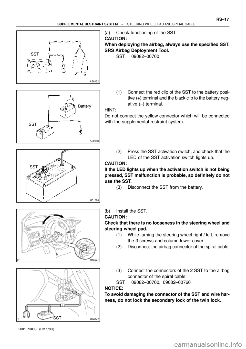
(a) Check functioning of the SST.
CAUTION:
When deploying the airbag, always use the specified SST:
SRS Airbag Deployment Tool.
SST 09082±00700
(1) Connect the red clip of the SST to the battery posi-
tive (+) terminal and the black clip to the battery neg-
ative (±) terminal.
HINT:
Do not connect the yellow connector which will be connected
with the supplemental restraint system.
(2) Press the SST activation switch, and check that the
LED of the SST activation switch lights up.
CAUTION:
If the LED lights up when the activation switch is not being
pressed, SST malfunction is probable, so definitely do not
use the SST.
(3) Disconnect the SST from the battery.
(b) Install the SST.
CAUTION:
Check that there is no looseness in the steering wheel and
steering wheel pad.
(1) While turning the steering wheel right / left, remove
the 3 screws and column lower cover.
(2) Disconnect the airbag connector of the spiral cable.
(3) Connect the connectors of the 2 SST to the airbag
connector of the spiral cable.
SST 09082±00700, 09082±00760
NOTICE:
To avoid damaging the connector of the SST and wire har-
ness, do not lock the secondary lock of the twin lock.
Page 1735 of 1943

R13455
10 m (33 ft) or more
SSTBattery
R06753
RS±18
± SUPPLEMENTAL RESTRAINT SYSTEMSTEERING WHEEL PAD AND SPIRAL CABLE
2001 PRIUS (RM778U)
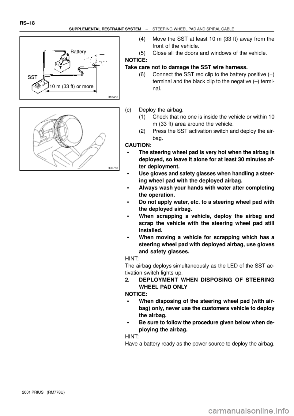
(4) Move the SST at least 10 m (33 ft) away from the
front of the vehicle.
(5) Close all the doors and windows of the vehicle.
NOTICE:
Take care not to damage the SST wire harness.
(6) Connect the SST red clip to the battery positive (+)
terminal and the black clip to the negative (±) termi-
nal.
(c) Deploy the airbag.
(1) Check that no one is inside the vehicle or within 10
m (33 ft) area around the vehicle.
(2) Press the SST activation switch and deploy the air-
bag.
CAUTION:
�The steering wheel pad is very hot when the airbag is
deployed, so leave it alone for at least 30 minutes af-
ter deployment.
�Use gloves and safety glasses when handling a steer-
ing wheel pad with the deployed airbag.
�Always wash your hands with water after completing
the operation.
�Do not apply water, etc. to a steering wheel pad with
the deployed airbag.
�When scrapping a vehicle, deploy the airbag and
scrap the vehicle with the steering wheel pad still
installed.
�When moving a vehicle for scrapping which has a
steering wheel pad with deployed airbag, use gloves
and safety glasses.
HINT:
The airbag deploys simultaneously as the LED of the SST ac-
tivation switch lights up.
2. DEPLOYMENT WHEN DISPOSING OF STEERING
WHEEL PAD ONLY
NOTICE:
�When disposing of the steering wheel pad (with air-
bag) only, never use the customers vehicle to deploy
the airbag.
�Be sure to follow the procedure given below when de-
ploying the airbag.
HINT:
Have a battery ready as the power source to deploy the airbag.