Page 256 of 1943

2001 PRIUS (EWD414U)
M OVERALL ELECTRICAL WIRING DIAGRAM
9
1011 12
19 PRIUS (
Cont' d)
9A 5A 1A
10 A 22 A 23 A 12 A12A8A4A
16 C 25 C 24 C 15 C11A7A3A
9C 28C 27C 18C10A6A2A
5D 13D 20D 19D 3B 10B 4B 1B
To Data Link
Connector 3
<2±5><2±6> Fr om Stop Light SW
<3±4>
24 B 16 B 14 B 22 B15 B 23 B
To Hybr id
Vehicle
Contr ol ECU
< 1±19> < 1±20> To EMPS ECU
< 20±4>
B16A15A 14A13A 19B20B 11B12B24 A21 B
1IB1 2IB1 5IB1
ABS
J10
JUNCTION
CONNECTOR
W±BB10 B11,
BRAKE ECUAB B13, D C , B12B 3 , C B 1 B 2,
BRAKE ACTUATORAB
B WRB WRB WRB WRP±B W± L GR± GG± W
LGVG RR G BRP
W±B L PL
PL Y BR
BR±BB W
(
Shielded) (
Shielded)
(
Shielded) (
Shielded) (
Shielded) (
Shielded)
(
Shielded) (
Shielded)(
Shielded) (
Shielded)
HVI + HVI ± HV O+ HVO± FL+ FL± FSS FR+ FR± RL+ RL ± RS S RR+ RR± RRO RLO VCM PMC E2 SG1 VREG PREG EREG SG2 VFR PFR EFR SG3 VRR PRR ERR SG4 TC D/ G TS STP
(
Shielded)
AA
A
221112
A 4
ABS SPEED
SENSOR FRONT LHA 5
ABS SPEED
SENSOR FRONT RHA23
ABS SPEED
SENSOR REAR L H12
A2 4
ABS SPEED
SENSOR REAR RH (
Shielded) A
W±B B± Y
W± B20 C
BZ6B
IG1
G
13 IA2
G1 2B±Y
DA
EB EB
B±Y
B±Y
J14 J15,
J UNCTI ON
CONNECTORAB
B14
BRAKE
WARNING BUZZERBUZZER
Page 260 of 1943

2001 PRIUS (EWD414U)
M OVERALL ELECTRICAL WIRING DIAGRAM
1
234
23 PRIUS(
Cont. next page)
5
3 1
2
5A AM1
A12H
D 1 C 1B1
120A MAIN1I15
IGNITION SW100 A DC/ DC
4 AM1
ST1IG1 ACC
2
2B 3 2D 6
IDCowl si de
panel LH 2K 8 1B 2
W±B W±B
B±Y W± GW
B WB±GJ11
JUNCTI ON
CONNECTOR BATTERYF18
FUSI BLE L I NK
BLOCK NO. 2IG1
RELA Y
F11 F12,
FUSI BLE LI NK
BL OCK NO. 1BCF13, D
10A GAUGE
2A 5
W±G
15A DOME
1J 722 A 21 A 13 A 20 A 12 A
14A 2A3A1A 7B6B1B9A 11ABUZZER2B 3B
D OORHEAD
Combination M eter Power Source
2A 4
2B 7
2G 2
2A 6 G
A
G
A G
B
G
B
2A 7
2B 6
IHRight kick
panel51
See Illumination
System< 8±4>
LL±YSee Back±Up
Light System< 6±3> See ABS System
< 19±4> See EMPS Syst em
< 20±4>
15 A
2J 62J82J916 A 9B
7. 5A ECU±B
2C 5
BR L L L L
R± GL V± W LL
L
L
L Y Y± B BR±R GR±B GR ±B
From
Navigation
ECU< 1 4±5 >
R± G R± G
GR GR± L
GR V±W
V±W
V± W
J27 J28,
JUNCTION
CONNECTORAB Fr om Engine
Control
Module< 2±13>From Hybr id
Vehicle Control
ECU< 1±19> F
F
J27
J UNCTI ON
CONNE CTOR BODY ECUB A B 8 B 9, F16
FUEL SENDER
E10
E NGI NE CONT ROL
MODUL E
G 1
GATEWAY ECUA 7
A/ C AMPL I FI ER
13 14 11
4 4
11MPX + MPD1 MP X2 MPX 1 MPD2
MPX ±
C10 C11,
COMBINATION METERAB 4IP15IP1L±WL±Y
48516
3
H 8
OD O/ TRI P SW
[ HA ZARD WARNI NG SW] VFD
TC ODO EA G
From Mul ti
Di spl ay
< 14±7> V± W
MP X+ MP X± B
FU± FU+ FUA
19 11 20
BR±R
Y± B
Y
L±Y
L±R
FUEL SENDER SENSOR
Page 261 of 1943
2001 PRIUS (EWD414U)
M
BRAKE SEAT BELT
(
Driver' s Seat)5
68 7
23 PRIUS (
Cont' d)
HI GH BEAM
TURN R
TURN L
SRS
ABS
MA LFUNCTI ON
I NDI CATOR LAMP
SEAT BEL T
(
Front
Pass enger' s Seat)
WATER TEMP.
(
Hi gh)
WATER TEMP.
(
Low)
CRUI SE
OUTPUT CONTROL
CHARGE
OI L
B 5 19A 18A 17A
4B 10A 16A
Combination M eter
See Tur n Signal
Light Sy stem< 5±4>See Headlight System
< 3±3> <4±4>
Se e SRS Syst em
< 21±3>
See Engine Cont rol
Sy st em< 2± 4> See ABS System
< 19±4> See SRS Sy st em
< 21±3>
C10 C11,
COMBI NATI ON METE RAB
Page 278 of 1943

NEW MODEL OUTLINE
SAFETY
182MO30182MO29
182MO31Side Impact Energy
19
Prius ± one step ahead of the rest even in the area of
safety.
Drive with the utmost peace of mind.
Passive Safety Body
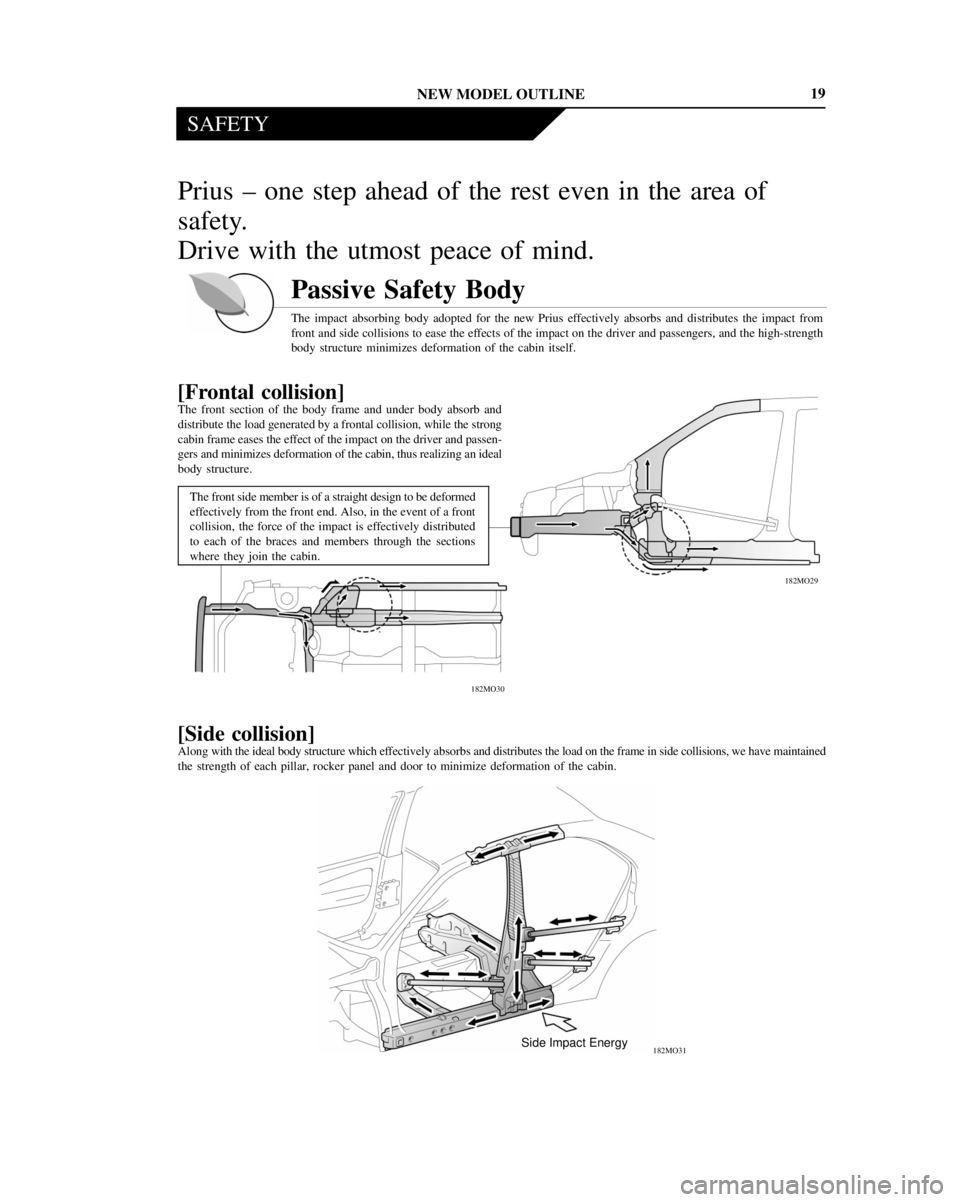
The impact absorbing body adopted for the new Prius effectively absorbs and distributes the impact from
front and side collisions to ease the effects of the impact on the driver and passengers, and the high-strength
body structure minimizes deformation of the cabin itself.
[Frontal collision]
The front section of the body frame and under body absorb and
distribute the load generated by a frontal collision, while the strong
cabin frame eases the effect of the impact on the driver and passen-
gers and minimizes deformation of the cabin, thus realizing an ideal
body structure.
The front side member is of a straight design to be deformed
effectively from the front end. Also, in the event of a front
collision, the force of the impact is effectively distributed
to each of the braces and members through the sections
where they join the cabin.
[Side collision]
Along with the ideal body structure which effectively absorbs and distributes the load on the frame in side collisions, we have maintained
the strength of each pillar, rocker panel and door to minimize deformation of the cabin.
Page 279 of 1943

NEW MODEL OUTLINE
SAFETY
182MO32
Aluminum EA Material
EA : Energy Absorbing
EA rib
(center pillar garnish pad) EA rib
(side rail front specer)EA rib
(side rail rear specer)
20
Head Impact Protection Structure
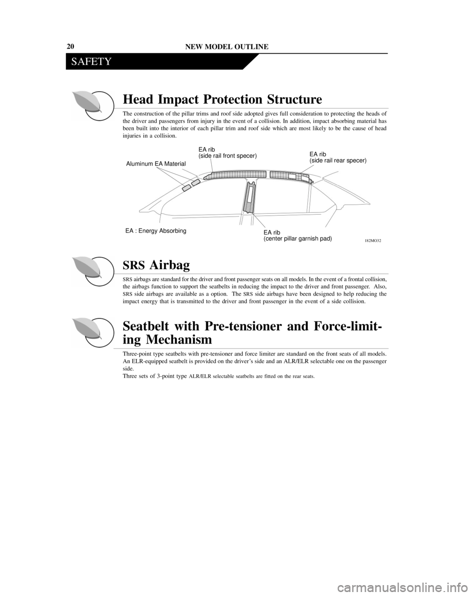
The construction of the pillar trims and roof side adopted gives full consideration to protecting the heads of
the driver and passengers from injury in the event of a collision. In addition, impact absorbing material has
been built into the interior of each pillar trim and roof side which are most likely to be the cause of head
injuries in a collision.
SRS Airbag
SRS airbags are standard for the driver and front passenger seats on all models. In the event of a frontal collision,
the airbags function to support the seatbelts in reducing the impact to the driver and front passenger. Also,
SRS side airbags are available as a option. The SRS side airbags have been designed to help reducing the
impact energy that is transmitted to the driver and front passenger in the event of a side collision.
Seatbelt with Pre-tensioner and Force-limit-
ing Mechanism
Three-point type seatbelts with pre-tensioner and force limiter are standard on the front seats of all models.
An ELR-equipped seatbelt is provided on the driver's side and an ALR/ELR selectable one on the passenger
side.
Three sets of 3-point type
ALR/ELR selectable seatbelts are fitted on the rear seats.
Page 298 of 1943

ENGINE ± 1NZ-FXE ENGINE
182EG17
182EG18
Cold Engine or Scavenging Mode
Warm Engine
Exhaust Gas57
c) Operation
Before the engine is started, the bypass valve remains open. When the engine is started, the ECM outputs
a signal to the VSV (for HC adsorber and catalyst system), which is applying a vacuum to the actuator.
As a result, the bypass valve closes.
Immediately after the engine has started, the exhaust gases pass through the HC adsorber in which HC
adsorbed and stored for a certain time (until the temperature of the HC adsorber rises). And prevent the
HC emitted from the tail pipe when the temperature of the TWCs are low.
After the TWC has warmed up, the VSV closes to the bypass valve to open. Then, as the temperature
of the rear TWC rises, the temperature of the HC absorber that surrounds it also rises, and the HC starts
to be desorbed, and cleaned by the TWC.
Furthermore, this system activates the VSV after the HC adsorber is warmed up and triggerd by decelera-
tion condition, the bypass valve is closed in order to scavenge the HC that remains in the HC adsorber.
Page 322 of 1943

THS (TOYOTA HYBRID SYSTEM) 24
�MAIN FUNCTIONS OF COMPONENTS
MG1Generates high-voltage electricity by being powered primarily by the engine.
Also functions as a starter to start the engine.
Hybrid
Trans-
axle
MG2
Primarily provide additional power to the engine in order to increase the
overall drive force. During braking, or when the accelerator pedal is not
depressed, it generates electricity to recharge the HV battery (Regenerative
brake system).
Planetary
Gear UnitDistributes the engine's drive force as appropriate to directly drive the vehicle
as well as the generator.
HV Battery
Supplies electric power to the MG2 during start-off, acceleration, and uphill
driving; recharged during braking or when the accelerator pedal is not
depressed.
InverterA device that converts the high-voltage DC (HV battery) into AC (MG1 and
MG2) and vice versa (Converts AC into DC).
Converter
Drops the high-voltage direct current (DC 273.6 V) into DC12 V in order to
supply electricity to body electrical components, as well as to recharge the
auxiliary battery (12 V).
HV (Hybrid Vehicle
Control) ECU
Information from each sensor as well as from the ECU (ECM, Battery ECU,
ABS ECU) is received, and based on this the required torque and output power
is calculated.
The HV ECU sends the calculated result to the actuators and controllers.
ECMSends a throttle open command to the electronically-controlled throttle in
accordance with the engine output request factor received from the HV ECU.
Battery ECUMonitors the charging condition of the HV battery.
Brake ECU
Controls the regenerative brake that is effected by the MG2 and the hydraulic
brake so that the total braking force equals that of a conventional vehicle that
is equipped only with hydraulic brakes.
Also, the brake ECU performs the ABS control conventionally.
Accelerator PedalConverts the accelerator angle into an electrical signal and outputs it to the HVAccelerator Pedal
Position Sensor
Converts the accelerator angle into an electrical signal and outputs it to the HV
ECU.
Shift Position SensorConverts the shift lever position into an electrical signal and outputs it to the
HV ECU.
SMR (System Main
Relay)Connects and disconnects the high-voltage power circuit through the use of
a signal from the HV ECU.
Service plugShuts off the high-voltage circuit of the HV battery when this plug is removed
for vehicle inspection or maintenance.
Page 326 of 1943

THS (TOYOTA HYBRID SYSTEM)
M-UU,
VU, WU
M-SDOWN
G-UU,
VU, WU
CONT 3
SENSORS ACTUATORS
INVERTER (for MG1)
INVERTER (for MG2)
G-SDOWN
DATA LINK CONNECTOR 3 SIL, TC
IGCT RELAYAUXILIARY
BATTERY MRELBATT
BATTERY ECU
ABS ECU
VEHICLE SPEED SIGNAL
(for Hybrid Transaxle)
ACCELERATOR PEDAL
POSITION SENSOR
SHIFT POSITION SENSOR
CRUISE CONTROL SWITCH
AIRBAG SENSOR ASSEMBLY
CIRCUIT BREAKER SENSOR
INTERLOCK SWITCH
(for Inverter Cover and Service Plug)
STOP LIGHT SWITCH
A / C ECU
CONVERTER NODD
MG2
M-REF,
SIN, COS
MG1
G-REF,
SIN, COS
ECM
COMBINATION METER
�Vehicle Speed Signal SPD
INVERTER
(for MG1)
INVERTER
(for MG2)
CONT 2
SYSTEM MAIN RELAY NO.1
SYSTEM MAIN RELAY NO.2
SYSTEM MAIN RELAY NO.3
G-MOTT
M-MOTT
CONT 1
HV ECU
HTD, DTH
HTB, BTH
VPA1, 2
SFT, P, R,
N, D, B
CCS
ABFCS
ACS
ILK
STP EGON
HTE, ETH
ACON
G-INVT
G-IU, IV, IW
M-SINV, FINV
M-INVT
M-IU, IV, IW
GO
SPDO
ESTP
IB
G-SINV, FINV
MG1
MG2
28
2. Construction
The configuration of the THS control system in the Prius is shown in the following chart.