Page 1864 of 1943
BO3PT±01
H15398
Matchmarks
H15396
± BODYFRONT WIPER AND WASHER
BO±35
2001 PRIUS (RM778U)
INSTALLATION
1. INSTALL WASHER NOZZLES
(a) Install the washer nozzles to the hood.
(b) Connect the washer hoses.
2. INSTALL OUTER FRONT COWL TOP PANEL
(a) Install the outer front cowl top panel with 6 bolts.
Torque: 5.4 N´m (55 kgf´cm, 48 in.´lbf)
(b) Push in the wiper motor wire harness with the grommet.
3. INSTALL ABS RELAY BLOCK
Install the ABS relay block with the 2 bolts.
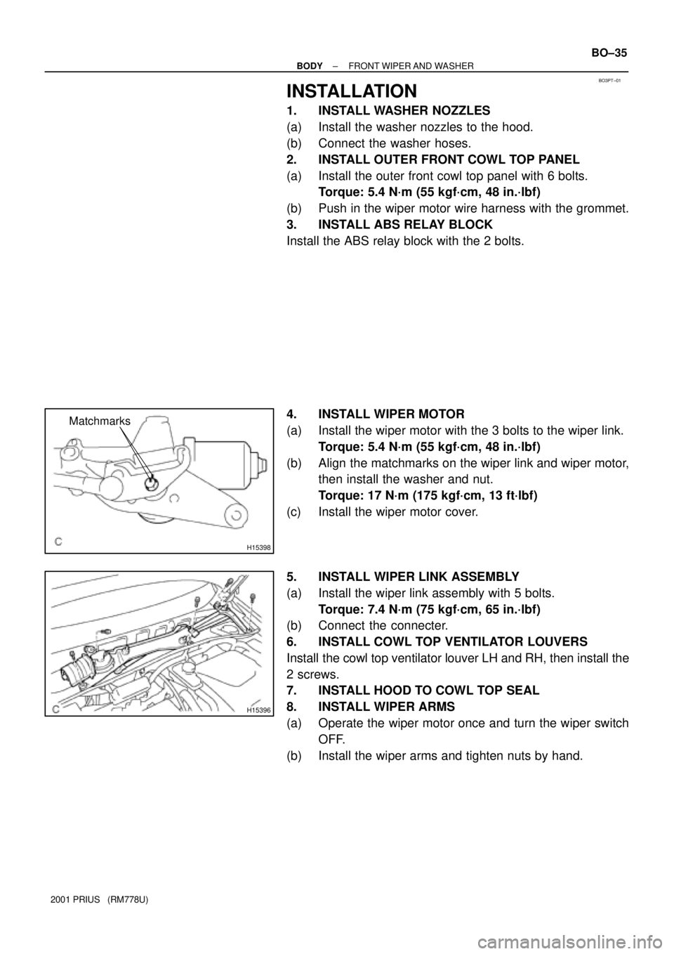
4. INSTALL WIPER MOTOR
(a) Install the wiper motor with the 3 bolts to the wiper link.
Torque: 5.4 N´m (55 kgf´cm, 48 in.´lbf)
(b) Align the matchmarks on the wiper link and wiper motor,
then install the washer and nut.
Torque: 17 N´m (175 kgf´cm, 13 ft´lbf)
(c) Install the wiper motor cover.
5. INSTALL WIPER LINK ASSEMBLY
(a) Install the wiper link assembly with 5 bolts.
Torque: 7.4 N´m (75 kgf´cm, 65 in.´lbf)
(b) Connect the connecter.
6. INSTALL COWL TOP VENTILATOR LOUVERS
Install the cowl top ventilator louver LH and RH, then install the
2 screws.
7. INSTALL HOOD TO COWL TOP SEAL
8. INSTALL WIPER ARMS
(a) Operate the wiper motor once and turn the wiper switch
OFF.
(b) Install the wiper arms and tighten nuts by hand.
Page 1865 of 1943
H15399Point Marks
BO±36
± BODYFRONT WIPER AND WASHER
2001 PRIUS (RM778U)
(c) Adjust the installation position of the arms to the positions
as shown in the illustration.
(d) Torque the 3 nuts.
Torque: 26 N´m (270 kgf´cm, 20 ft´lbf)
(e) Install the wiper arm head cap.
Page 1873 of 1943
H15405
w/o Rain garter:
Windshield Glass
Body
w/ Rain garter:Windshield Moulding
Windshield Moulding
Windshield Glass
Body
H15399Point Marks
BO±50
± BODYWINDSHIELD
2001 PRIUS (RM778U)
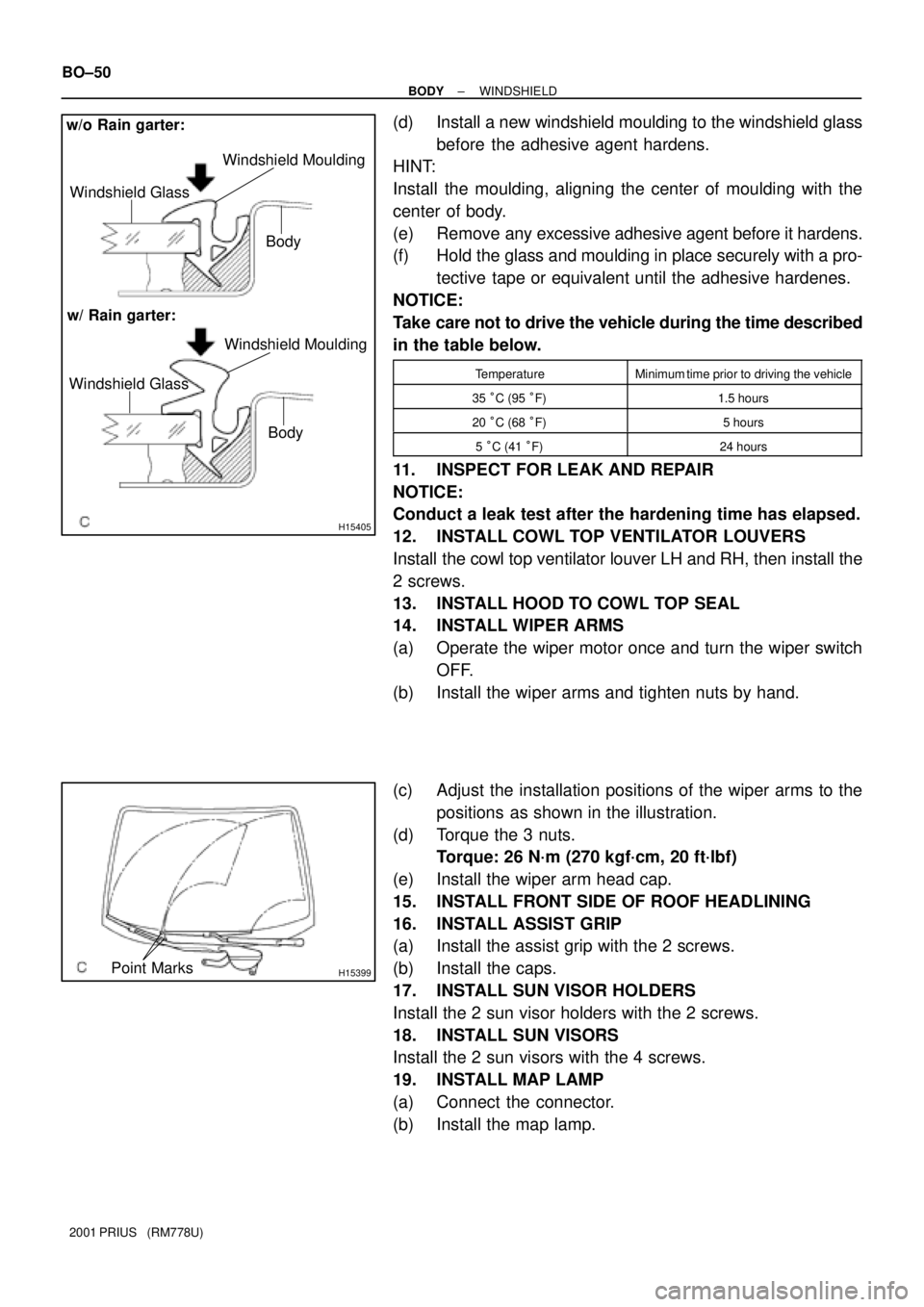
(d) Install a new windshield moulding to the windshield glass
before the adhesive agent hardens.
HINT:
Install the moulding, aligning the center of moulding with the
center of body.
(e) Remove any excessive adhesive agent before it hardens.
(f) Hold the glass and moulding in place securely with a pro-
tective tape or equivalent until the adhesive hardenes.
NOTICE:
Take care not to drive the vehicle during the time described
in the table below.
TemperatureMinimum time prior to driving the vehicle
35 °C (95 °F)1.5 hours
20 °C (68 °F)5 hours
5 °C (41 °F)24 hours
11. INSPECT FOR LEAK AND REPAIR
NOTICE:
Conduct a leak test after the hardening time has elapsed.
12. INSTALL COWL TOP VENTILATOR LOUVERS
Install the cowl top ventilator louver LH and RH, then install the
2 screws.
13. INSTALL HOOD TO COWL TOP SEAL
14. INSTALL WIPER ARMS
(a) Operate the wiper motor once and turn the wiper switch
OFF.
(b) Install the wiper arms and tighten nuts by hand.
(c) Adjust the installation positions of the wiper arms to the
positions as shown in the illustration.
(d) Torque the 3 nuts.
Torque: 26 N´m (270 kgf´cm, 20 ft´lbf)
(e) Install the wiper arm head cap.
15. INSTALL FRONT SIDE OF ROOF HEADLINING
16. INSTALL ASSIST GRIP
(a) Install the assist grip with the 2 screws.
(b) Install the caps.
17. INSTALL SUN VISOR HOLDERS
Install the 2 sun visor holders with the 2 screws.
18. INSTALL SUN VISORS
Install the 2 sun visors with the 4 screws.
19. INSTALL MAP LAMP
(a) Connect the connector.
(b) Install the map lamp.
Page 1874 of 1943
H15357
H13603
2 Clips
± BODYWINDSHIELD
BO±51
2001 PRIUS (RM778U)
20. INSTALL INNER REAR VIEW MIRROR
(a) Install the inner rear view mirror with the 2 screws.
Torque: 2.9 N´m (30 kgf´cm, 26 in.´lbf)
(b) Install the cover.
21. INSTALL FRONT PILLAR GARNISH AND NO. 1 FRONT
PILLAR SPACERS
(a) Install the 2 No. 1 front pillar spacers and 4 screws.
(b) Install the front pillar garnish to the body.
(c) Employ the same manner described above to the other
side.
Page 1880 of 1943
H15384
4 Clips
H15383
H13694
5 Clips BO±58
± BODYBACK WINDOW GLASS
2001 PRIUS (RM778U)
12. INSTALL REAR PART OF ROOF HEADLINING
Install the 2 clips.
13. INSTALL REAR ASSIST GRIPS
(a) Install the 2 rear assist grips with the 4 screws.
(b) Install the caps.
14. INSTALL SILENCER PAD
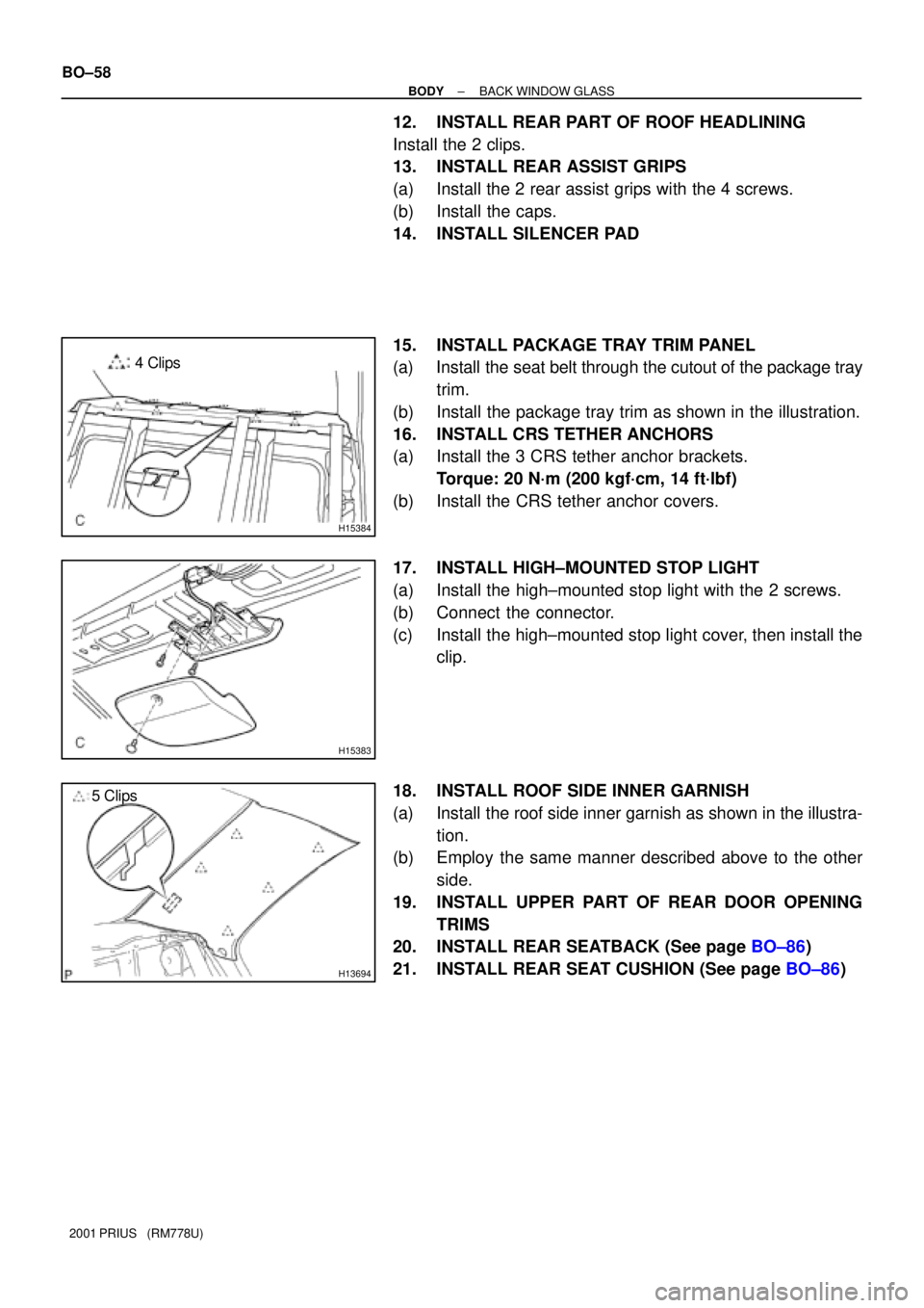
15. INSTALL PACKAGE TRAY TRIM PANEL
(a) Install the seat belt through the cutout of the package tray
trim.
(b) Install the package tray trim as shown in the illustration.
16. INSTALL CRS TETHER ANCHORS
(a) Install the 3 CRS tether anchor brackets.
Torque: 20 N´m (200 kgf´cm, 14 ft´lbf)
(b) Install the CRS tether anchor covers.
17. INSTALL HIGH±MOUNTED STOP LIGHT
(a) Install the high±mounted stop light with the 2 screws.
(b) Connect the connector.
(c) Install the high±mounted stop light cover, then install the
clip.
18. INSTALL ROOF SIDE INNER GARNISH
(a) Install the roof side inner garnish as shown in the illustra-
tion.
(b) Employ the same manner described above to the other
side.
19. INSTALL UPPER PART OF REAR DOOR OPENING
TRIMS
20. INSTALL REAR SEATBACK (See page BO±86)
21. INSTALL REAR SEAT CUSHION (See page BO±86)
Page 1881 of 1943
BO3TB±01
H15446
Passenger Airbag Assembly
Front Pillar Garnish
No. 2 Side Defroster Nozzle
No. 3 Register
Cluster Finish
Panel
Front Pillar
Garnish
Combination Meter
No. 1 Side Defroster Nozzle
Instrument Panel
No. 1 Register
Instrument Panel
Reinforcement
Upper Column Cover
Spiral Cable
Lower Column Cover
Lower Finish Panel
Front Door Scuff Plate
Cowl Side
TrimHood Lock Release LeverFront Door
Scuff Plate
Rear Console Box
Console Compartment
Door
Lower Center
Cluster Finish Panel
Glove Compartment
Door
Cowl Side Trim
Steering Wheel
Steering Wheel Pad
Finish Panel
No. 1 BraceCluster Finish
Panel Assembly
Radio Tuner Opening Cover
Hazard Warning Switch
N´m (kgf´cm, ft´lbf)
: Spesified torque
A
A
B
BNNC
HH
G
GG
G
D
D
II
G
G
D
D
I
O
50 (510, 37)
20 (204, 15)
KK
w/ Glove compartment door reinforcement:
Glove Compartment Door Reinforcement
L
L
HH
LL
EE
FF
± BODYINSTRUMENT PANEL
BO±59
1844 Author�: Date�:
2001 PRIUS (RM778U)
INSTRUMENT PANEL
COMPONENTS
Page 1885 of 1943
H15508
H15509
H154392 Clips
H154406 Clips
H15441
2 Clips
± BODYINSTRUMENT PANEL
BO±63
2001 PRIUS (RM778U)
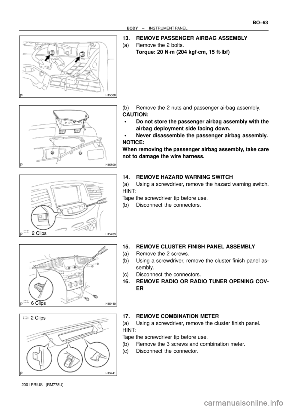
13. REMOVE PASSENGER AIRBAG ASSEMBLY
(a) Remove the 2 bolts.
Torque: 20 N´m (204 kgf´cm, 15 ft´lbf)
(b) Remove the 2 nuts and passenger airbag assembly.
CAUTION:
�Do not store the passenger airbag assembly with the
airbag deployment side facing down.
�Never disassemble the passenger airbag assembly.
NOTICE:
When removing the passenger airbag assembly, take care
not to damage the wire harness.
14. REMOVE HAZARD WARNING SWITCH
(a) Using a screwdriver, remove the hazard warning switch.
HINT:
Tape the screwdriver tip before use.
(b) Disconnect the connectors.
15. REMOVE CLUSTER FINISH PANEL ASSEMBLY
(a) Remove the 2 screws.
(b) Using a screwdriver, remove the cluster finish panel as-
sembly.
(c) Disconnect the connectors.
16. REMOVE RADIO OR RADIO TUNER OPENING COV-
ER
17. REMOVE COMBINATION METER
(a) Using a screwdriver, remove the cluster finish panel.
HINT:
Tape the screwdriver tip before use.
(b) Remove the 3 screws and combination meter.
(c) Disconnect the connector.
Page 1889 of 1943
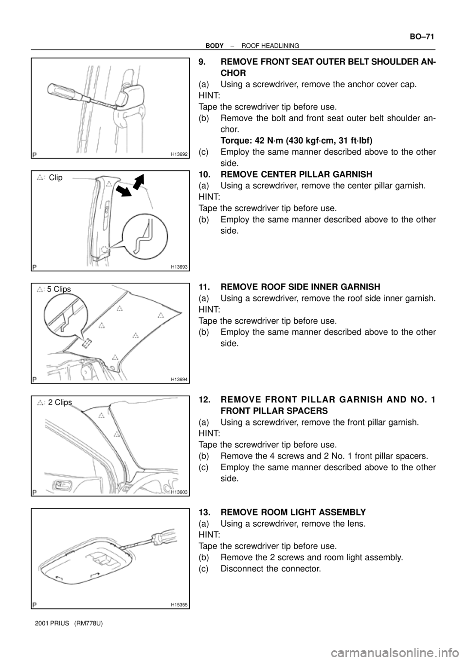
H13692
H13693
Clip
H13694
5 Clips
H13603
2 Clips
H15355
± BODYROOF HEADLINING
BO±71
2001 PRIUS (RM778U)
9. REMOVE FRONT SEAT OUTER BELT SHOULDER AN-
CHOR
(a) Using a screwdriver, remove the anchor cover cap.
HINT:
Tape the screwdriver tip before use.
(b) Remove the bolt and front seat outer belt shoulder an-
chor.
Torque: 42 N´m (430 kgf´cm, 31 ft´lbf)
(c) Employ the same manner described above to the other
side.
10. REMOVE CENTER PILLAR GARNISH
(a) Using a screwdriver, remove the center pillar garnish.
HINT:
Tape the screwdriver tip before use.
(b) Employ the same manner described above to the other
side.
11. REMOVE ROOF SIDE INNER GARNISH
(a) Using a screwdriver, remove the roof side inner garnish.
HINT:
Tape the screwdriver tip before use.
(b) Employ the same manner described above to the other
side.
12. REMOVE FRONT PILLAR GARNISH AND NO. 1
FRONT PILLAR SPACERS
(a) Using a screwdriver, remove the front pillar garnish.
HINT:
Tape the screwdriver tip before use.
(b) Remove the 4 screws and 2 No. 1 front pillar spacers.
(c) Employ the same manner described above to the other
side.
13. REMOVE ROOM LIGHT ASSEMBLY
(a) Using a screwdriver, remove the lens.
HINT:
Tape the screwdriver tip before use.
(b) Remove the 2 screws and room light assembly.
(c) Disconnect the connector.