Page 1890 of 1943

14. REMOVE INNER REAR VIEW MIRROR
(a) Using a moulding remover, remove the cover as shown in
the illustration.")
H15356
H15357
H15383
H15358P
H15359P BO±72
± BODYROOF HEADLINING
2001 PRIUS (RM778U)
14. REMOVE INNER REAR VIEW MIRROR
(a) Using a moulding remover, remove the cover as shown in
the illustration.
(b) Remove the 2 screws and inner rear view mirror.
Torque: 2.9 N´m (30 kgf´cm, 26 in.´lbf)
15. REMOVE MAP LAMP
(a) Using a screwdriver, remove the map lamp.
(b) Disconnect the map lamp connector.
16. REMOVE ASSIST GRIPS
(a) Using a screwdriver, remove the caps.
HINT:
Tape the screwdriver tip before use.
(b) Remove the 6 bolts and 3 assist grips.
17. REMOVE HIGH±MOUNTED STOP LIGHT
(a) Remove the clip then pull the high±mounted stoplight
cover.
(b) Disconnect the connector.
(c) Remove the 2 screws and high±mounted stop light.
18. REMOVE SUN VISORS
(a) Remove the 4 screws and pull the sun visors downward.
(b) Disconnect the connectors.
19. REMOVE SUN VISOR HOLDERS
Remove the 2 screws and 2 holders.
20. REMOVE ROOF HEADLINING
(a) Remove the 2 clips.
(b) Pull the roof headlining downward to remove it.
21. REMOVE FRONT AND REAR SIDE RAIL SPACER
(a) Remove the 4 screws and front side rail spacer.
(b) Remove the 4 screws and rear side rail spacer.
(c) Employ the same manner described above to the other
side.
Page 1894 of 1943
H15368
H15458
H15461
AB
BO±80
± BODYFRONT SEAT
2001 PRIUS (RM778U)
(d) Install the headrest supports.
7. w/o Side airbag:
INSTALL SEATBACK ASSEMBLY
Install seatback assembly with 4 bolts.
Torque: 43 N´m (440 kgf´cm, 32 ft´lbf)
8. w/ Side airbag:
INSTALL SEATBACK ASSEMBLY
(a) Install the 4 bolts and seatback assembly.
(b) Install the side airbag connector from the under the seat.
(c) Install the clamp from wire harness of side airbag re-
moved under the seat.
9. INSTALL SEAT CUSHION INNER SHIELD
10. INSTALL FRONT SEAT INNER BELT
Install the front seat inner belt with the bolt.
Torque: 41 N´m (420 kgf´cm, 30 ft´lbf)
11. INSTALL SEAT CUSHION SHIELD
Install the 2 screws and seat cushion sushion shield as shown
in the illustration.
HINT:
Install the seat cushion shield in order A, B as shown in the il-
lustration.
12. INSTALL RECLINING RELEASE HANDLE
13. INSTALL HEADREST
Page 1904 of 1943

INSTALLATION
NOTICE:
�Never use seat belt pretensioner from another")
BO3TA±01
H15467H15360H16310
Driver's side:
Except driver's side:
H15375
± BODYSEAT BELT PRETENSIONER
BO±99
2001 PRIUS (RM778U)
INSTALLATION
NOTICE:
�Never use seat belt pretensioner from another ve-
hicle. When replacing parts, replace them with new
parts.
�Make sure that the front seat outer belt is installed
with the specified torque.
�If the front seat outer belt has been dropped, or there
are cracks, dents or other defects in the case or con-
nector, replace the front seat outer belt with a new
one.
�When installing the front seat outer belt, take care that
the wiring does not interfere with other parts and is
not pinched between other parts.
1. INSTALL FRONT SEAT OUTER BELT
(a) Install the retractor of front seat outer belt.
(1) Install the retractor of front seat outer belt with the
bolt.
Torque: 4.9 N´m (50 kgf´cm, 43 in.´lbf)
(2) Connect the pretensioner connector as shown in
the illustration.
(3) Connect the tension reducer connector.
NOTICE:
When handling the pretensioner connector and tensionre-
ducer, take care not to damage the wire harness.
(b) Install the floor anchor with the bolt.
Torque: 42 N´m (430 kgf´cm, 31 ft´lbf)
(c) Install the floor anchor cover.
(d) Install the shoulder anchor with the bolt.
Torque: 42 N´m (430 kgf´cm, 31 ft´lbf)
(e) Install the shoulder anchor cover.
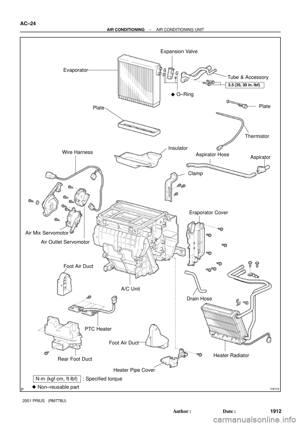
Page 1919 of 1943
I18112
N´m (kgf´cm, ft´lbf) : Specified torque
�Non±reusable partEvaporatorExpansion Valve
Tube & Accessory
Plate
Thermistor
Aspirator
Eraporator CoverAspirator Hose
Clamp Insulator Plate
Wire Harness
Air Mix Servomotor
Air Outlet Servomotor
Foot Air Duct
PTC HeaterA/C Unit
Foot Air Duct
Heater Pipe CoverDrain Hose
Heater Radiator
Rear Foot DuctO±Ring
3.5 (35, 30 in.´lbf)
�
AC±24
± AIR CONDITIONINGAIR CONDITIONING UNIT
1912 Author�: Date�:
2001 PRIUS (RM778U)
Page 1922 of 1943
AC35U±01
I11223
SST
I18010
SST
I18012
N20013
R±Shape
RotorSnap Ring
Compressor
I18011
AC±40
± AIR CONDITIONINGCOMPRESSOR AND MAGNETIC CLUTCH
2001 PRIUS (RM778U)
DISASSEMBLY
1. REMOVE PRESSURE PLATE
(a) Using SST and a socket wrench, remove the shaft bolt.
SST 07112±76050
Torque: 13.2 N´m (135 kgf´cm, 9 ft´lbf)
(b) Install SST to the pressure plate.
SST 07112±66040
(c) Using SST and a socket wrench, remove the pressure
plate.
SST 07112±76050, 07112±66040
(d) Remove the shims from the shaft.
2. REMOVE ROTOR
(a) Remove the snap ring.
NOTICE:
At the time of reassembly, please refer to the following
item.
The snap ring should be installed so that its beveled side
faces up.
(b) Using a plastic hammer, tap the rotor off the shaft.
NOTICE:
Be careful not to damage the pulley when tapping on the ro-
tor.
Page 1924 of 1943
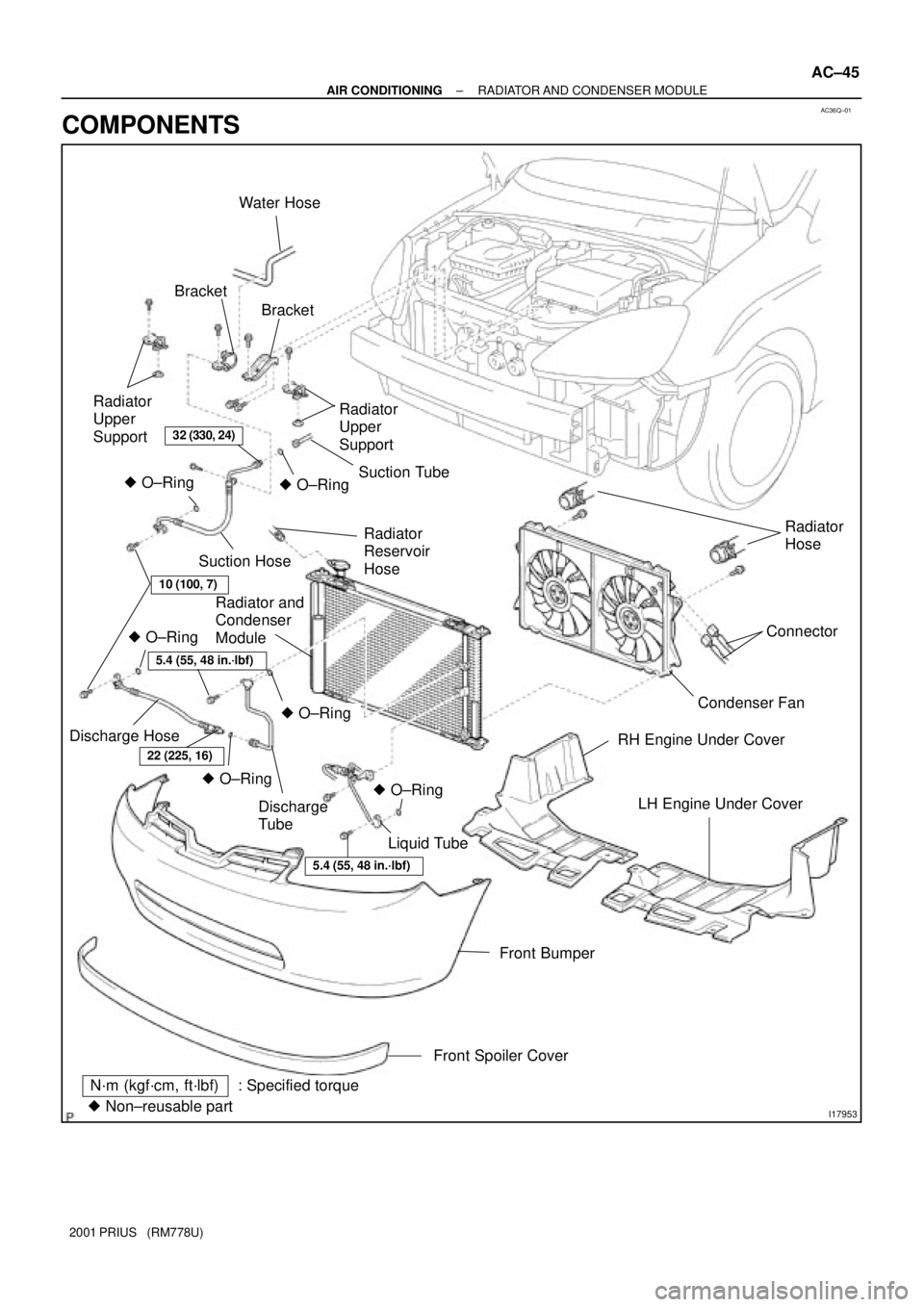
AC36Q±01
I17953
N´m (kgf´cm, ft´lbf): Specified torque
� Non±reusable partBracket Water Hose
Radiator
Upper
Support
� O±RingRadiator
Reservoir
Hose Suction Hose
Radiator and
Condenser
Module
Discharge Hose
Liquid Tube Discharge
Tube
5.4 (55, 48 in.´lbf)
22 (225, 16)
5.4 (55, 48 in.´lbf)
� O±Ring
10 (100, 7)
� O±Ring
� O±RingSuction Tube
� O±Ring
Bracket
Radiator
Upper
Support
Radiator
Hose
Condenser FanConnector
RH Engine Under Cover
LH Engine Under Cover
Front Bumper� O±Ring
32 (330, 24)
Front Spoiler Cover
± AIR CONDITIONINGRADIATOR AND CONDENSER MODULE
AC±45
2001 PRIUS (RM778U)
COMPONENTS
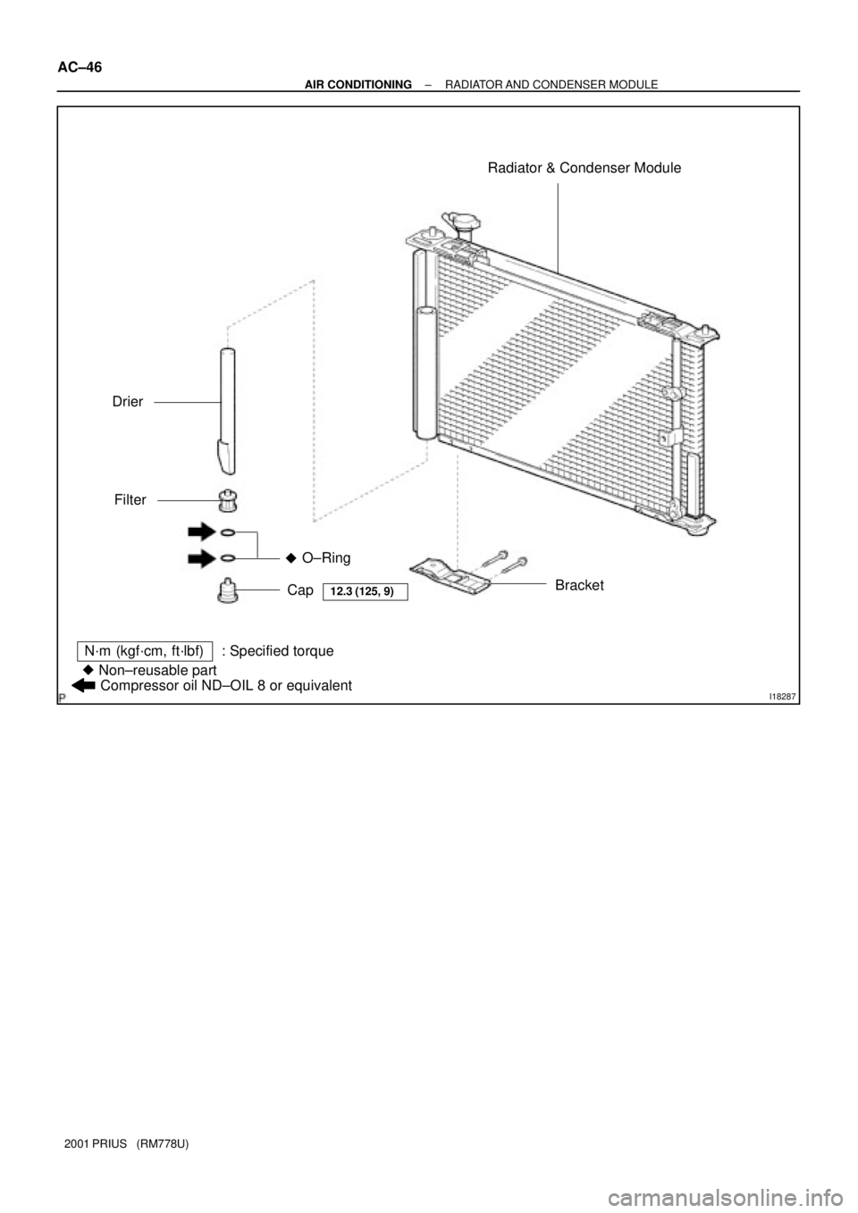
Page 1925 of 1943
I18287
Radiator & Condenser Module
Bracket Drier
Filter
O±Ring
Cap
12.3 (125, 9)
N´m (kgf´cm, ft´lbf): Specified torque
� Non±reusable part�
Compressor oil ND±OIL 8 or equivalent
AC±46
± AIR CONDITIONINGRADIATOR AND CONDENSER MODULE
2001 PRIUS (RM778U)
Page 1926 of 1943

REMOVAL
1. DISCHARGE REFRIGERANT FROM REFRIGERATION
SYSTEM
HINT:
At the time of installation, plea")
AC36R±01
I17955
I17954
± AIR CONDITIONINGRADIATOR AND CONDENSER MODULE
AC±47
2001 PRIUS (RM778U)
REMOVAL
1. DISCHARGE REFRIGERANT FROM REFRIGERATION
SYSTEM
HINT:
At the time of installation, please refer to the following item.
Evacuate air from refrigeration system.
Charge system with refrigerant and inspect for leakage of refrig-
erant.
Specified amount: 500 ± 50 g (17.64 ± 1.76 oz.)
2. DRAIN ENGINE COOLANT FROM RADIATOR
HINT:
It is not necessary to drain out all the coolant.
3. REMOVE CONDENSER FAN ASSEMBLY
(See Page AC±69)
4. REMOVE FRONT BUMPER (See Page BO±4)
5. REMOVE RADIATOR RESERVOIR HOSE
6. DISCONNECT DISCHARGE AND LIQUID TUBE
(a) Remove the 2 bolts and disconnect discharge and liquid
tube.
Torque: 5.4 N´m (55 kgf´cm, 48 in.´lbf)
NOTICE:
Cap open the fittings immediately to keep moisture or dirt
out of the system.
HINT:
At the time of installation, please refer to the following item.
Lubricate 2 new O±rings with compressor oil and install them
to the tubes.
(b) Remove the bolt.
(c) Disconnect the liquid tube and remove the bracket.
7. REMOVE RADIATOR UPPER SUPPORT
Remove the 2 bolts and 2 radiator upper supports.

(d) Install the headrest supports.
7. w/o Side airbag:
INSTALL SEATBACK ASSEMBLY
Install seatback assembly with 4 bolts.
Torque:")

DISASSEMBLY
1. REMOVE PRESSURE PL")