Page 1711 of 1943
F12262
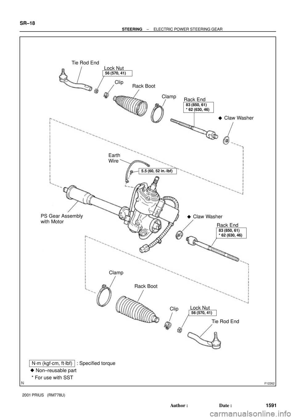
Tie Rod End
Clip
Rack Boot
Clamp
Rack End
PS Gear Assembly
with Motor
Claw Washer
�
83 (850, 61)
* 62 (630, 46)
Claw Washer
�
Rack End83 (850, 61)
* 62 (630, 46)
Clamp
Rack Boot
Clip
Tie Rod End
Lock Nut56 (570, 41)
Lock Nut56 (570, 41)
N´m (kgf´cm, ft´lbf) : Specified torque
Non±reusable part
* For use with SST �
5.5 (60, 52 in.´lbf)
Earth
Wire
SR±18
± STEERINGELECTRIC POWER STEERING GEAR
1591 Author�: Date�:
2001 PRIUS (RM778U)
Page 1712 of 1943

REMOVAL
NOTICE:
Remove the steering wheel assembly before the steering
gear removal, because there is p")
SR1BL±01
F12196
F12214
A
B
± STEERINGELECTRIC POWER STEERING GEAR
SR±19
2001 PRIUS (RM778U)
REMOVAL
NOTICE:
Remove the steering wheel assembly before the steering
gear removal, because there is possibility of breaking of
the spiral cable.
1. PLACE FRONT WHEELS FACING STRAIGHT AHEAD
2. REMOVE STEERING WHEEL PAD (See page SR±6)
3. REMOVE STEERING WHEEL (See page SR±6)
4. REMOVE RH AND LH ENGINE UNDER COVERS
5. DISCONNECT RH AND LH TIE ROD ENDS (See page
SA±9)
6. DISCONNECT STABILIZER BAR (See page SA±41)
7. DISCONNECT LOWER SUSPENSION ARM FROM
LOWER BALL JOINT (See page SA±41)
8. DISCONNECT 2 CONNECTORS AND EMPS BRACK-
ET
(a) Disconnect the 2 connectors.
(b) Disconnect the 2 clamps.
(c) Remove the bolt and disconnect the earth wire.
(d) Remove the 2 bolts and EMPS bracket.
9. DISCONNECT NO. 2 INTERMEDIATE SHAFT AS-
SEMBLY
(a) Place the matchmarks on the No. 2 intermediate shaft as-
sembly and control valve shaft.
(b) Loosen the bolt ºAº and remove the bolt ºBº then discon-
nect the No. 2 intermediate shaft assembly from the con-
trol valve shaft.
10. DISCONNECT TORQUE ROD (See page SA±41)
11. REMOVE SUSPENSION MEMBER AND ELECTRIC
POWER STEERING GEAR ASSEMBLY (See page
SA±41)
12. REMOVE ELECTRIC POWER STEERING GEAR AS-
SEMBLY
(a) Remove the stabilizer bar (See page SA±41).
Page 1716 of 1943

REASSEMBLY
NOTICE:
When using a vise, do not overtighten it.
1. INSTALL EARTH WIRE")
SR1BN±01
F12267
F12268
Fulcrum LengthSST
F12269
± STEERINGELECTRIC POWER STEERING GEAR
SR±23
2001 PRIUS (RM778U)
REASSEMBLY
NOTICE:
When using a vise, do not overtighten it.
1. INSTALL EARTH WIRE
Install the earth wire with the bolt.
Torque: 5.5 N´m (60 kgf´cm, 52 in.´lbf)
2. INSTALL RH AND LH CLAW WASHERS AND RACK
ENDS
(a) Install a new claw washer and temporarily install the rack
end.
HINT:
Align the claws of the claw washer with the steering rack
grooves.
(b) Using a spanner, hold the steering rack steadily and using
SST, torque the rack end.
SST 09922 ± 10010
Torque: 62 N´m (630 kgf´cm, 46 ft´lbf)
NOTICE:
Use SST 09922 ± 10010 in the direction shown in the il-
lustration.
HINT:
Use a torque wrench with a fulcrum length of 380 mm (14.96
in.).
(c) Using a brass bar and a hammer, stake the claw washer.
NOTICE:
Avoid any impact on the steering rack.
(d) Employ the same manner described above to the other
side.
3. INSTALL RH AND LH RACK BOOTS, CLIPS AND
CLAMPS
(a) Ensure that the steering rack hole is not clogged with
grease.
HINT:
If the hole is clogged, the pressure inside the boot will change
after it is assembled and the steering wheel is turned.
(b) Install the boot, clip and clamp.
NOTICE:
Be careful not to damage or twist the boot.
Page 1717 of 1943
F07501
Matchmarks
SR±24
± STEERINGELECTRIC POWER STEERING GEAR
2001 PRIUS (RM778U)
(c) Employ the same manner described above to the other
side.
4. INSTALL RH AND LH TIE ROD ENDS AND LOCK NUT
(a) Screw the lock nut and tie rod end onto the rack end and
the matchmarks aligned.
(b) After adjusting toe±in. torque the nut (See page
SA±4).
(c) Employ the same manner described above to the other
side.
Page 1718 of 1943
SR1BO±01
F12847
Front
F12197
F15034
Serrated Part
F15035
Main Shaft Lower
Dust Seal
Body
Engine Compartment SideCab Side
± STEERINGELECTRIC POWER STEERING GEAR
SR±25
2001 PRIUS (RM778U)
INSTALLATION
1. INSTALL ELECTRIC POWER STEERING GEAR AS-
SEMBLY
(a) Install the grommet and bracket to the electric power
steering gear assembly.
HINT:
Install the bracket with the inscribed mark facing to the front of
the vehicle.
(b) Install the electric power steering gear assembly with the
4 new bolts to the front suspension member.
Torque: 83 N´m (850 kgf´cm, 61 ft´lbf)
(c) Install the stabilizer bar (See page SA±43).
(d) To prevent the main shaft lower dust seal from damaging,
wind vinyl tape on the serrated part of the control valve
shaft.
(e) Turn over the main shaft lower dust seal from the engine
compartment side to the cab.
2. INSTALL SUSPENSION MEMBER AND ELECTRIC
POWER STEERING GEAR ASSEMBLY (See page
SA±43)
3. CONNECT TORQUE ROD (See page SA±43)
Page 1719 of 1943

4. CONNECT EMPS BRACKET AND 2 CONNECTORS
(a) Connect the EMPS bracket with the 2 bolts.
Torque: 5.5 N�")
F12196
F12214
Matchmarks
A
B
SR±26
± STEERINGELECTRIC POWER STEERING GEAR
2001 PRIUS (RM778U)
4. CONNECT EMPS BRACKET AND 2 CONNECTORS
(a) Connect the EMPS bracket with the 2 bolts.
Torque: 5.5 N´m (60 kgf´cm, 52 in.´lbf)
(b) Connect the earth wire with the bolt.
Torque: 5.5 N´m (60 kgf´cm, 52 in.´lbf)
(c) Connect the 2 clamps.
(d) Connect the 2 connectors.
5. CONNECT LOWER SUSPENSION ARM TO LOWER
BALL JOINT (See page SA±43)
6. CONNECT STABILIZER BAR (See page SA±43)
7. CONNECT NO. 2 INTERMEDIATE SHAFT ASSEMBLY
(a) Put the dust seal back to the engine compartment side.
(b) Remove the vinyl tape from the serrated part of the control
valve shaft.
(c) Align the matchmarks on the No. 2 intermediate shaft as-
sembly and control valve shaft.
(d) Install the bolt ºBº and torque the bolt ºAº.
Torque: 35 N´m (360 kgf´cm, 22 ft´lbf)
8. CONNECT RH AND LH TIE ROD ENDS
(See page SA±14)
9. PLACE FRONT WHEELS FACING STRAIGHT AHEAD
HINT:
Do it with the front of the vehicle jacked up.
10. CENTER SPIRAL CABLE (See page SR±14)
11. INSTALL STEERING WHEEL
(a) Align the matchmarks on the steering wheel and steering
column main shaft.
(b) Temporarily tighten the steering wheel set nut.
12. CHECK STEERING WHEEL CENTER POINT
13. TORQUE STEERING WHEEL SET NUT
Torque: 50 N´m (510 kgf´cm, 37 ft´lbf)
14. INSTALL STEERING WHEEL PAD (See page SR±14)
15. CHECK FRONT WHEEL ALIGNMENT
16. PERFORM CALIBRATION OF TORQUE SENSOR
ZERO POINT (See page DI±454)
Page 1756 of 1943
RS0RB±01
H15368
H11975
H11974
H15461
± SUPPLEMENTAL RESTRAINT SYSTEMSIDE AIRBAG ASSEMBLY
RS±49
2001 PRIUS (RM778U)
INSTALLATION
NOTICE:
Never use airbag parts from another vehicle. When replac-
ing parts, replace them with new parts.
1. INSTALL SEATBACK ASSEMBLY
(a) Install the seatback assembly to the seat adjuster with the
4 bolts.
Torque: 43 N´m (440 kgf´cm, 32 ft´lbf)
(b) Install 5 new hog rings.
HINT:
When installing the hog rings, take care to prevent wrinkles as
little as possible.
2. INSTALL SEAT CUSHION ASSEMBLY
Install the seat cushion assembly.
3. INSTALL FRONT SEAT CUSHION SHIELDS
(a) Install the inner front seat cushion shield with the 2
screws.
(b) Employ the same manner described above to the other
side.
4. INSTALL RECLINING ADJUSTER RELEASE HANDLE
Page 1757 of 1943
H15460
RS±50
± SUPPLEMENTAL RESTRAINT SYSTEMSIDE AIRBAG ASSEMBLY
2001 PRIUS (RM778U)
5. INSTALL FRONT SEAT
NOTICE:
When mounting the seat to the vehicle, take care not to
damage the airbag wire harness.
(a) Connect the side airbag connector.
(b) Slide the front seat to the most front position.
NOTICE:
Make sure that seat adjuster locks.
(c) Without holding the seat track handle, mount the seat to
the vehicle.
HINT:
If holding the seat track handle, the adjusted rearmost position
slip off.
(d) Tighten the bolts on the front side temporarily, from the
bolt on the inner side tighten them completely.
Torque: 37 N´m (375 kgf´cm, 27 ft´lbf)
(e) Slide the seat to the most front position to install the bolts
on the rear side.
Torque: 37 N´m (375 kgf´cm, 27 ft´lbf)
(f) Install the 2 seat track covers.

(c) Employ the same manner described above to the other
side.
4. INSTALL RH AND LH TIE ROD ENDS AND LOCK NUT
(a)")

INSTALLA")

INSTALLATION
NOTICE:
Never use airbag parts from another vehicle. When replac-
i")

5. INSTALL FRONT SEAT
NOTICE:
When mounting the seat to the vehicle, take care not to
damage the airbag wire ha")