Page 1658 of 1943
SA3213
Front A
DB
C
F11574
F11575
SA0028
Front AB
A B
A: Inside
B: Outside SA±6
± SUSPENSION AND AXLEFRONT WHEEL ALIGNMENT
1456 Author�: Date�:
2001 PRIUS (RM778U)
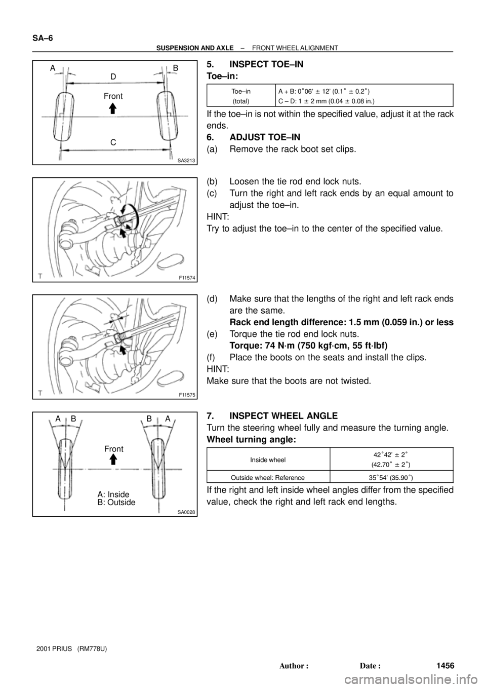
5. INSPECT TOE±IN
Toe±in:
Toe±in
(total)A + B: 0°06' ± 12' (0.1° ± 0.2°)
C ± D: 1 ± 2 mm (0.04 ± 0.08 in.)
If the toe±in is not within the specified value, adjust it at the rack
ends.
6. ADJUST TOE±IN
(a) Remove the rack boot set clips.
(b) Loosen the tie rod end lock nuts.
(c) Turn the right and left rack ends by an equal amount to
adjust the toe±in.
HINT:
Try to adjust the toe±in to the center of the specified value.
(d) Make sure that the lengths of the right and left rack ends
are the same.
Rack end length difference: 1.5 mm (0.059 in.) or less
(e) Torque the tie rod end lock nuts.
Torque: 74 N´m (750 kgf´cm, 55 ft´lbf)
(f) Place the boots on the seats and install the clips.
HINT:
Make sure that the boots are not twisted.
7. INSPECT WHEEL ANGLE
Turn the steering wheel fully and measure the turning angle.
Wheel turning angle:
Inside wheel42°42' ± 2°
(42.70° ± 2°)
Outside wheel: Reference35°54' (35.90°)
If the right and left inside wheel angles differ from the specified
value, check the right and left rack end lengths.
Page 1659 of 1943
SA1ZR±01
F08617
R14731
Backlash:Deviation:
F12940SST
± SUSPENSION AND AXLEFRONT AXLE HUB
SA±9
2001 PRIUS (RM778U)
REMOVAL
1. REMOVE FRONT WHEEL
Torque: 103 N´m (1,050 kgf´cm, 76 ft´lbf)
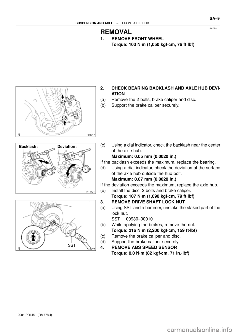
2. CHECK BEARING BACKLASH AND AXLE HUB DEVI-
ATION
(a) Remove the 2 bolts, brake caliper and disc.
(b) Support the brake caliper securely.
(c) Using a dial indicator, check the backlash near the center
of the axle hub.
Maximum: 0.05 mm (0.0020 in.)
If the backlash exceeds the maximum, replace the bearing.
(d) Using a dial indicator, check the deviation at the surface
of the axle hub outside the hub bolt.
Maximum: 0.07 mm (0.0028 in.)
If the deviation exceeds the maximum, replace the axle hub.
(e) Install the disc, 2 bolts and brake caliper.
Torque: 107 N´m (1,090 kgf´cm, 79 ft´lbf)
3. REMOVE DRIVE SHAFT LOCK NUT
(a) Using SST and a hammer, unstake the staked part of the
lock nut.
SST 09930±00010
(b) While applying the brakes, remove the nut.
Torque: 216 N´m (2,200 kgf´cm, 159 ft´lbf)
(c) Remove the brake caliper and disc.
(d) Support the brake caliper securely.
4. REMOVE ABS SPEED SENSOR
Torque: 8.0 N´m (82 kgf´cm, 71 in.´lbf)
Page 1660 of 1943
F12941
F11576
SST
F11617
F12941
SA±10
± SUSPENSION AND AXLEFRONT AXLE HUB
2001 PRIUS (RM778U)
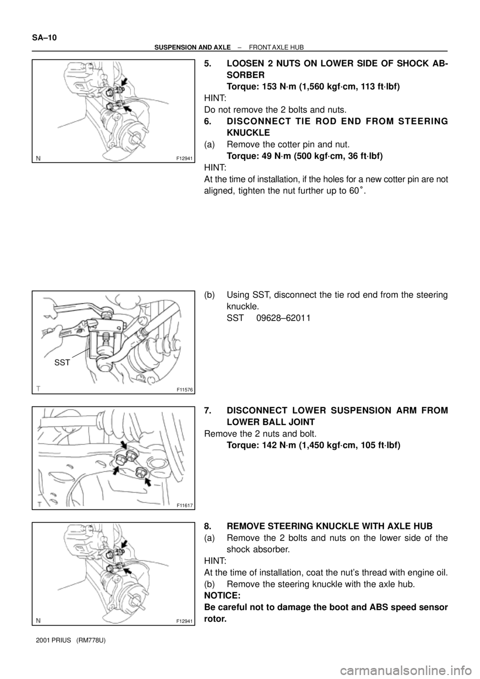
5. LOOSEN 2 NUTS ON LOWER SIDE OF SHOCK AB-
SORBER
Torque: 153 N´m (1,560 kgf´cm, 113 ft´lbf)
HINT:
Do not remove the 2 bolts and nuts.
6. DISCONNECT TIE ROD END FROM STEERING
KNUCKLE
(a) Remove the cotter pin and nut.
Torque: 49 N´m (500 kgf´cm, 36 ft´lbf)
HINT:
At the time of installation, if the holes for a new cotter pin are not
aligned, tighten the nut further up to 60°.
(b) Using SST, disconnect the tie rod end from the steering
knuckle.
SST 09628±62011
7. DISCONNECT LOWER SUSPENSION ARM FROM
LOWER BALL JOINT
Remove the 2 nuts and bolt.
Torque: 142 N´m (1,450 kgf´cm, 105 ft´lbf)
8. REMOVE STEERING KNUCKLE WITH AXLE HUB
(a) Remove the 2 bolts and nuts on the lower side of the
shock absorber.
HINT:
At the time of installation, coat the nut's thread with engine oil.
(b) Remove the steering knuckle with the axle hub.
NOTICE:
Be careful not to damage the boot and ABS speed sensor
rotor.
Page 1663 of 1943
SA20B±01
FA1535
SST
F12940SST
F11576
SST
± SUSPENSION AND AXLEFRONT DRIVE SHAFT
SA±17
2001 PRIUS (RM778U)
REMOVAL
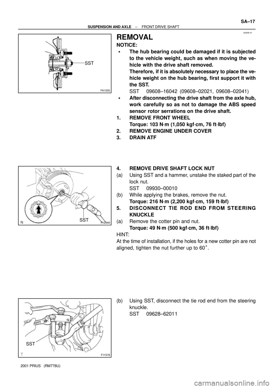
NOTICE:
�The hub bearing could be damaged if it is subjected
to the vehicle weight, such as when moving the ve-
hicle with the drive shaft removed.
Therefore, if it is absolutely necessary to place the ve-
hicle weight on the hub bearing, first support it with
the SST.
SST 09608±16042 (09608±02021, 09608±02041)
�After disconnecting the drive shaft from the axle hub,
work carefully so as not to damage the ABS speed
sensor rotor serrations on the drive shaft.
1. REMOVE FRONT WHEEL
Torque: 103 N´m (1,050 kgf´cm, 76 ft´lbf)
2. REMOVE ENGINE UNDER COVER
3. DRAIN ATF
4. REMOVE DRIVE SHAFT LOCK NUT
(a) Using SST and a hammer, unstake the staked part of the
lock nut.
SST 09930±00010
(b) While applying the brakes, remove the nut.
Torque: 216 N´m (2,200 kgf´cm, 159 ft´lbf)
5. DISCONNECT TIE ROD END FROM STEERING
KNUCKLE
(a) Remove the cotter pin and nut.
Torque: 49 N´m (500 kgf´cm, 36 ft´lbf)
HINT:
At the time of installation, if the holes for a new cotter pin are not
aligned, tighten the nut further up to 60°.
(b) Using SST, disconnect the tie rod end from the steering
knuckle.
SST 09628±62011
Page 1664 of 1943
F11617
F13342
F11614SST
SA±18
± SUSPENSION AND AXLEFRONT DRIVE SHAFT
2001 PRIUS (RM778U)
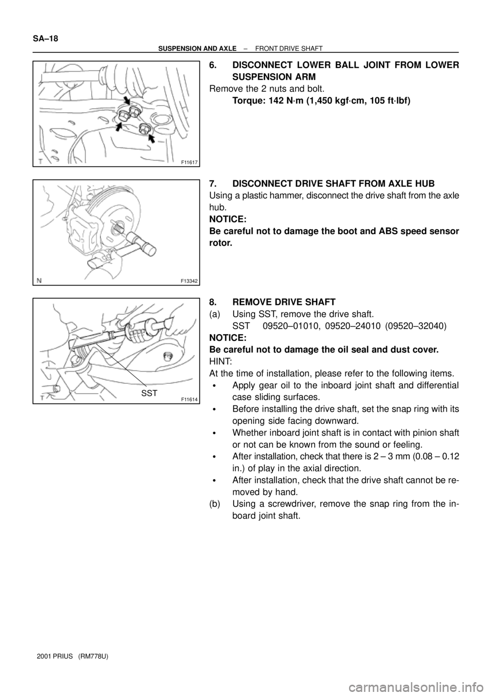
6. DISCONNECT LOWER BALL JOINT FROM LOWER
SUSPENSION ARM
Remove the 2 nuts and bolt.
Torque: 142 N´m (1,450 kgf´cm, 105 ft´lbf)
7. DISCONNECT DRIVE SHAFT FROM AXLE HUB
Using a plastic hammer, disconnect the drive shaft from the axle
hub.
NOTICE:
Be careful not to damage the boot and ABS speed sensor
rotor.
8. REMOVE DRIVE SHAFT
(a) Using SST, remove the drive shaft.
SST 09520±01010, 09520±24010 (09520±32040)
NOTICE:
Be careful not to damage the oil seal and dust cover.
HINT:
At the time of installation, please refer to the following items.
�Apply gear oil to the inboard joint shaft and differential
case sliding surfaces.
�Before installing the drive shaft, set the snap ring with its
opening side facing downward.
�Whether inboard joint shaft is in contact with pinion shaft
or not can be known from the sound or feeling.
�After installation, check that there is 2 ± 3 mm (0.08 ± 0.12
in.) of play in the axial direction.
�After installation, check that the drive shaft cannot be re-
moved by hand.
(b) Using a screwdriver, remove the snap ring from the in-
board joint shaft.
Page 1669 of 1943
SA1P6±02
F11581
SST
F11582
Out
F11583
F08624
SST
± SUSPENSION AND AXLEFRONT SHOCK ABSORBER
SA±29
2001 PRIUS (RM778U)
REASSEMBLY
1. INSTALL LOWER INSULATOR ONTO SHOCK AB-
SORBER
2. INSTALL SPRING BUMPER TO PISTON ROD
3. INSTALL COIL SPRING
(a) Using SST, compress the coil spring.
SST 09727±30021 (09727±00010, 09727±00021,
09727±00031)
NOTICE:
Do not use an impact wrench. It will damage the SST.
(b) Install the coil spring to the shock absorber.
HINT:
Fit the lower end of the coil spring into the gap of the spring low-
er seat.
(c) Install the upper insulator as shown in the illustration.
(d) Install the spring seat to the shock absorber with the º
º
mark facing to the outside of the vehicle.
(e) Install the dust seal and suspension support.
(f) Using SST to hold the suspension support, install a new
nut.
SST 09729±22031
Torque: 47 N´m (475 kgf´cm, 34 ft´lbf)
(g) Remove the SST.
SST 09727±30021 (09727±00010, 09727±00021,
09727±00031)
Page 1671 of 1943
SA1ZW±01
F11576
SST
F11616
F11617
F11586
± SUSPENSION AND AXLEFRONT LOWER SUSPENSION ARM
SA±33
2001 PRIUS (RM778U)
REMOVAL
1. REMOVE FRONT WHEEL
Torque: 103 N´m (1,050 kgf´cm, 76 ft´lbf)
2. REMOVE ENGINE UNDER COVER
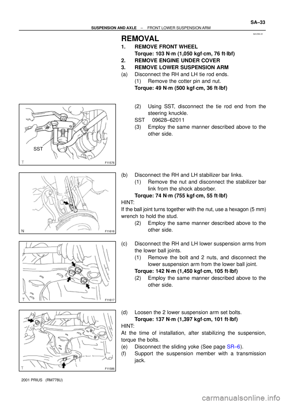
3. REMOVE LOWER SUSPENSION ARM
(a) Disconnect the RH and LH tie rod ends.
(1) Remove the cotter pin and nut.
Torque: 49 N´m (500 kgf´cm, 36 ft´lbf)
(2) Using SST, disconnect the tie rod end from the
steering knuckle.
SST 09628±62011
(3) Employ the same manner described above to the
other side.
(b) Disconnect the RH and LH stabilizer bar links.
(1) Remove the nut and disconnect the stabilizer bar
link from the shock absorber.
Torque: 74 N´m (755 kgf´cm, 55 ft´lbf)
HINT:
If the ball joint turns together with the nut, use a hexagon (5 mm)
wrench to hold the stud.
(2) Employ the same manner described above to the
other side.
(c) Disconnect the RH and LH lower suspension arms from
the lower ball joints.
(1) Remove the bolt and 2 nuts, and disconnect the
lower suspension arm from the lower ball joint.
Torque: 142 N´m (1,450 kgf´cm, 105 ft´lbf)
(2) Employ the same manner described above to the
other side.
(d) Loosen the 2 lower suspension arm set bolts.
Torque: 137 N´m (1,397 kgf´cm, 101 ft´lbf)
HINT:
At the time of installation, after stabilizing the suspension,
torque the bolts.
(e) Disconnect the sliding yoke (See page SR±6).
(f) Support the suspension member with a transmission
jack.
Page 1672 of 1943
F12936
F12933
SA±34
± SUSPENSION AND AXLEFRONT LOWER SUSPENSION ARM
2001 PRIUS (RM778U)
(g) Remove the bolt and nut, disconnect the torque rod from
the suspension member.
Torque: 100 N´m (1,150 kgf´cm, 83 ft´lbf)
(h) Remove the 4 bolts and disconnect the suspension mem-
ber from the body.
Torque:
Front side: 113 N´m (1,152 kgf´cm, 83 ft´lbf)
Rear side: 157 N´m (1,600 kgf´cm, 116 ft´lbf)
(i) Remove the 2 lower suspension arm set bolts and discon-
nect the lower suspension arm from suspension member.