Page 962 of 1943
F12443
ABS Solenoid
RelayEngine Room R/B
No. 3
Brake
Actuator
Brake ECU
ASTBS3
ASTAST
DI±384
± DIAGNOSTICSANTI±LOCK BRAKE SYSTEM WITH EBD & RBS
2001 PRIUS (RM778U)
4 Check continuity between terminals 3 of engine room R/B No. 3 (for ABS sole-
noid relay) and terminal AST of brake ECU.
CHECK:
Check continuity between terminal 3 of engine room R/B No. 3
(for ABS solenoid relay) and terminal AST of brake ECU.
OK:
Continuity
HINT:
There is a resistance of approx. 33 W between terminals BS and
AST of the brake actuator.
NG Repair or replace harness or brake actuator.
OK
5 Check for open and short circuit in harness and connector between ABS sole-
noid relay and brake ECU (See page IN±41).
NG Repair or replace harness or connector.
OK
If the same code is still output after the DTC is deleted, check the contact condition of each con-
nection. If the connections are normal, the ECU may be defective.
Page 963 of 1943

F12673
B±G
F111
L4 Instrument
Panel J/B
DC/DC FL Block No. 1
3
Brake
Combination Meter
W±B
Brake Fluid
Level Warning
Switch7Brake ECU
LBL
C11
J7
J/C AM1162K
IE 2A
ID22B11
WR±Y
MAINLG±R
12
14
A W±G B±Y
IG1
RelayBRL
B12
C11
C10
C105 Body ECU
B8 B8
15
BR2
2 W±B
A A
J1
J/C AW±BInstrument
Panel J/B
Battery FL
Block
No. 21
F13
Ignition Switch
24
2H 2B 2D
2K2A 5 1
3 6
5 1
3
27
8GAUGE
LMultiplex Communication Circuit
IH 2B 6 1
J11
J/CGR±B GR
± DIAGNOSTICSANTI±LOCK BRAKE SYSTEM WITH EBD & RBS
DI±385
2001 PRIUS (RM778U)
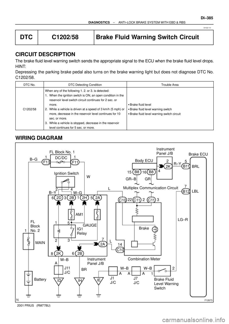
DTC C1202/58 Brake Fluid Warning Switch Circuit
CIRCUIT DESCRIPTION
The brake fluid level warning switch sends the appropriate signal to the ECU when the brake fluid level drops.
HINT:
Depressing the parking brake pedal also turns on the brake warning light but does not diagnose DTC No.
C1202/58.
DTC No.DTC Detecting ConditionTrouble Area
C1202/58
When any of the following 1. 2. or 3. is detected:
1. When the ignition switch is ON, an open condition in the
reservoir level switch circuit continues for 2 sec. or
more.
2. While a vehicle is driven at a speed of 3 km/h (5 mph) or
more, decrease in the reservoir level continues for 10
sec. or more.
3. While a vehicle is stopped, decrease in the reservoir
level continues for 5 sec. or more.
�Brake fluid level
�Brake fluid level warning switch
�Brake fluid level warning switch circuit
WIRING DIAGRAM
DI1GZ±10
Page 979 of 1943

F12678
Ignition SwitchFL Block No. 1
BatteryB±Y
2 4
W±B
W±B
W±B J15
6 1
IG1
GND3
GND1 GND4 DC/DC
AM1
ECU±IG
IDJ/C
A
A AW±B
GND2
B10 F131
12
2B 1 B±G
IEBrake ECU
817 W±GW
Instrument Panel J/B31 2H 2I 2D
2KF11
FL
Block
No. 2B11 B11
B11
B10
J1
J/C J11
J/C6
68 J14
213
35
IG1
RelayB±Y
B±Y
W±BE D
MAIN DI±402
± DIAGNOSTICSANTI±LOCK BRAKE SYSTEM WITH EBD & RBS
2001 PRIUS (RM778U)
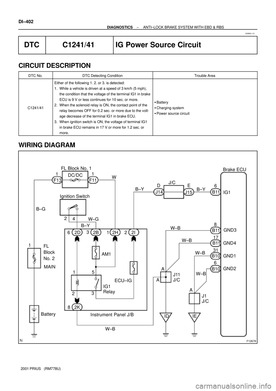
DTC C1241/41 IG Power Source Circuit
CIRCUIT DESCRIPTION
DTC No.DTC Detecting ConditionTrouble Area
C1241/41
Either of the following 1. 2. or 3. is detected:
1. While a vehicle is driven at a speed of 3 km/h (5 mph),
the condition that the voltage of the terminal IG1 in brake
ECU is 9 V or less continues for 10 sec. or more.
2. When the solenoid relay is ON, the contact point of the
relay becomes OFF for 0.2 sec. or more due to the volt-
age decrease of the terminal IG1 in brake ECU.
3. When ignition switch is ON, the voltage of terminal IG1
in brake ECU remains in 17 V or more for 1.2 sec. or
more.
�Battery
�Charging system
�Power source circuit
WIRING DIAGRAM
DI0WV±13
Page 988 of 1943

F12681
Brake ECU
B2
2 6
AA 1
1 ABS
No. 2
Engine Room J/B22
2 2
22
14
22
Y 1
3 FL
Block No. 12
2
J1
J/CL±O
5IA2
LG±R
13R1+
R2+ Y±B
W±L F12
IE2 G±W W±L
Battery 1B
6
H6 H6
B±G 1K
Hydraulic Brake
Booster7
W±BY±G14
3Y±G
MR2MR1
MTT
MT+
MT± 29
27
28
18 ABS
No. 3
FL
Block No. 2B
1K
F13H5
H6
H5
H5
H5
W±B W±B
AAY±B
B11
B13
B10
B13
B10
B10
B10
J7
J/CEngine
Room
R/B No. 2 Hydro
Motor
Relay
No. 2 Hydro
Motor
Relay
No. 1 1
23
43
4 2 1
G
MAIN
± DIAGNOSTICSANTI±LOCK BRAKE SYSTEM WITH EBD & RBS
DI±411
2001 PRIUS (RM778U)
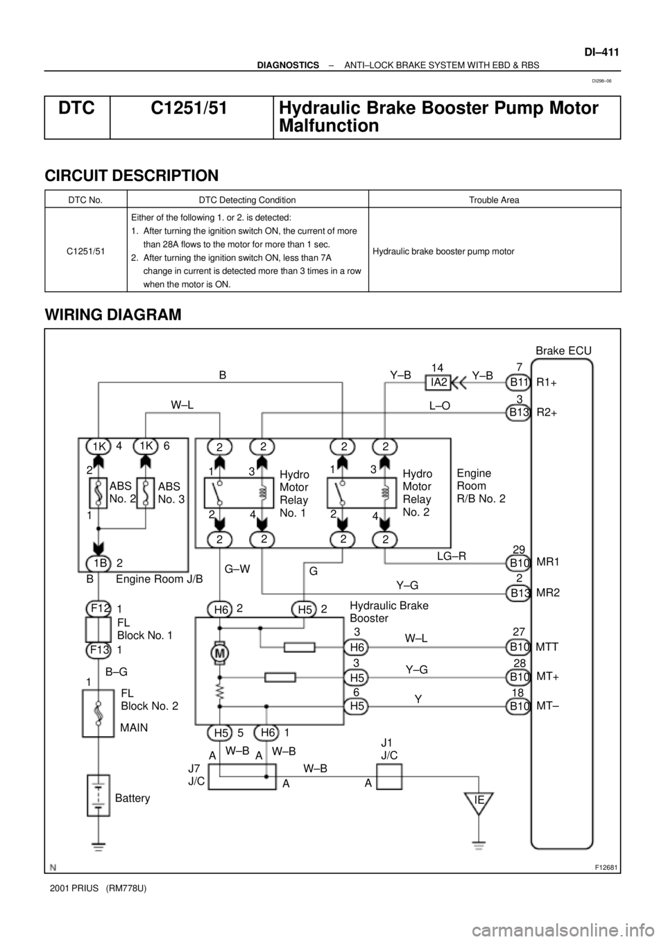
DTC C1251/51 Hydraulic Brake Booster Pump Motor
Malfunction
CIRCUIT DESCRIPTION
DTC No.DTC Detecting ConditionTrouble Area
C1251/51
Either of the following 1. or 2. is detected:
1. After turning the ignition switch ON, the current of more
than 28A flows to the motor for more than 1 sec.
2. After turning the ignition switch ON, less than 7A
change in current is detected more than 3 times in a row
when the motor is ON.
Hydraulic brake booster pump motor
WIRING DIAGRAM
DI298±06
Page 991 of 1943
F12681
Brake ECU
B2
2 6
AA 1
1 ABS
No. 2
Engine Room J/B22
2 2
22
14
22
Y 1
3 FL
Block No. 12
2
J1
J/CL±O
5IA2
LG±R
13R1+
R2+ Y±B
W±L F12
IE2 G±W W±L
Battery 1B
6
H6 H6
B±G 1K
Hydraulic Brake
Booster7
W±BY±G14
3Y±G
MR2MR1
MTT
MT+
MT± 29
27
28
18 ABS
No. 3
FL
Block No. 2B
1K
F13H5
H6
H5
H5
H5
W±B W±B
AAY±B
B11
B13
B10
B13
B10
B10
B10
J7
J/CEngine
Room
R/B No. 2 Hydro
Motor
Relay
No. 2 Hydro
Motor
Relay
No. 1 1
23
43
4 2 1
G
MAIN DI±414
± DIAGNOSTICSANTI±LOCK BRAKE SYSTEM WITH EBD & RBS
2001 PRIUS (RM778U)
DTC C1252/52 Hydraulic Brake Booster Pump Motor
ON Time Abnormally Long
CIRCUIT DESCRIPTION
DTC No.DTC Detecting ConditionTrouble Area
C1252/52After turning the ignition switch ON, when the power is sup-
plied to the pump motor for more than 5 minutes.�Hydraulic brake booster pump motor
�Hydraulic brake booster pump motor circuit
�Pressure switch (PH or PL)
WIRING DIAGRAM
DI6AB±02
Page 992 of 1943
F12408
BM2
BM1
GND2 GND1
± DIAGNOSTICSANTI±LOCK BRAKE SYSTEM WITH EBD & RBS
DI±415
2001 PRIUS (RM778U)
INSPECTION PROCEDURE
1 Check operation of hydraulic brake booster pump motor.
PREPARATION:
Disconnect the 2 connectors from the hydraulic brake booster.
CHECK:
Connect battery positive � lead to BM1 or BM2 terminal and
battery negative � lead to GND1 or GND2 terminal of the hy-
draulic brake booster (pump motor) connector.
OK:
The operation sound of the pump motor should be
heard.
NG Go to step 9.
OK
2 Check for short circuit in harness and connector between BM1 or BM2 of hy-
draulic brake booster and hydro motor relay (See page IN±41).
NG Repair or replace harness or connector.
OK
3 Check for short circuit in harness and connector between MTT of hydraulic
brake booster and brake ECU (See page IN±41).
NG Repair or replace harness or connector.
OK
Page 996 of 1943
F00044
1
2
3 4
(+) (±) Continuity1 2
3 4
1
2
3 4 Open
Continuity
± DIAGNOSTICSANTI±LOCK BRAKE SYSTEM WITH EBD & RBS
DI±419
2001 PRIUS (RM778U)
7 Check hydro motor relay No. 1 and No. 2.
PREPARATION:
Remove the hydro motor relay No. 1 and No. 2 from the engine
room R/B No. 2.
CHECK:
Check continuity between each pair of terminal of motor relay.
OK:
Terminals 3 and 4Continuity
(Reference value *)
Terminals 1 and 2Open
*
Reference value:
Hydro motor relay No. 1 62 W
Hydro motor relay No. 2 54 W
CHECK:
(a) Apply battery positive voltage between terminals 3 and 4.
(b) Check continuity between terminals.
OK:
Terminals 1 and 2Continuity
NG Replace hydro motor relay.
OK
8 Check for short circuit in harness and connector between hydro motor relay No.
1, No. 2 and brake ECU (See page IN±41).
NG Repair or replace harness or connector.
OK
Check and replace brake ECU.
Page 998 of 1943

± DIAGNOSTICSANTI±LOCK BRAKE SYSTEM WITH EBD & RBS
DI±421
2001 PRIUS (RM778U)
DTC C1253/53 Hydro Motor Relay Circuit
CIRCUIT DESCRIPTION
The hydro motor relay supplies power to the hydraulic brake booster pump motor. While the ABS & EBD &
RBS are activated, the ECU switches the motor relay ON and operates the hydraulic brake booster pump
motor.
DTC No.DTC Detecting ConditionTrouble Area
C1253/53
When any of the following 1. through 4. is detected:
1. After turning the ignition switch ON, open in the relay
coil is detected for more than 1 sec.
2. When the pressure switch does not control motor
driving, the status that the motor relay is always ON
continues for more than 1 sec. due to short circuit.
3. When the pressure switch (PH) detects the low
pressure or while the pump motor operates to increase
the pressure, the status that the motor relay does not
turn ON continues for more than 0.2 sec.
4. When pressure switch does not control motor driving,
the status that the motor relay is always ON due to the
welded contact continues for more than 2 sec.
�Hydro motor relay
�Hydro motor relay circuit
DI29A±13