Page 1020 of 1943

F00043
1 2 3
4 5 6
1 2 3
4 5 6
1 2 3
4
65 Open
Continuity
Continuity
Continuity
Open
(+)(±)
(+) (±)1 2 3
4 5 6 Continuity
DI±444
± DIAGNOSTICSANTI±LOCK BRAKE SYSTEM WITH EBD & RBS
2001 PRIUS (RM778U)
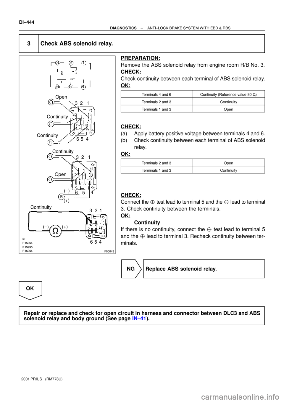
3 Check ABS solenoid relay.
PREPARATION:
Remove the ABS solenoid relay from engine room R/B No. 3.
CHECK:
Check continuity between each terminal of ABS solenoid relay.
OK:
Terminals 4 and 6Continuity (Reference value 80 W)
Terminals 2 and 3Continuity
Terminals 1 and 3Open
CHECK:
(a) Apply battery positive voltage between terminals 4 and 6.
(b) Check continuity between each terminal of ABS solenoid
relay.
OK:
Terminals 2 and 3Open
Terminals 1 and 3Continuity
CHECK:
Connect the � test lead to terminal 5 and the � lead to terminal
3. Check continuity between the terminals.
OK:
Continuity
If there is no continuity, connect the � test lead to terminal 5
and the � lead to terminal 3. Recheck continuity between ter-
minals.
NG Replace ABS solenoid relay.
OK
Repair or replace and check for open circuit in harness and connector between DLC3 and ABS
solenoid relay and body ground (See page IN±41).
Page 1021 of 1943
± DIAGNOSTICSANTI±LOCK BRAKE SYSTEM WITH EBD & RBS
DI±445
2001 PRIUS (RM778U)
4 Check that the brake ECU connectors are securely connected to the brake ECU.
NO Connect the connector to the brake ECU.
YES
5 Check operation of the ABS warning light (See step 1).
OK Check and replace brake ECU.
NG
6 Is DTC output?
Check DTC on page DI±353.
YES Repair circuit indicated by the output code.
NO
7 Check ABS solenoid relay (See step 3).
NG Replace ABS solenoid relay.
OK
Check for short circuit in harness and connector between DLC3 and ABS solenoid relay (See
page IN±41).
Page 1022 of 1943
F12684
Brake Fluid Level
Warning Switch
IG1
Relay FL Block No. 2
Body ECU
Multiplex Communication CircuitR±Y
BrakePKB
E
83
GAUGE5
WJ12
J/C Parking
Brake Switch
2 1
1C10
2A7
LG±R
A 4BRL Brake ECU
W±GB12
6
Battery
IE LBL B12 B1113
R±Y R±Y
R±Y E
J7
J/C
J1
J/C
J11
J/C 2D2B
2H2K
2K5
23 15
2A7 AM1
C10C11C11
143
2
22 2
W±BB±Y
L
BRA A
A
W±BW±B 21 IA2 18
MAIN
B±GFL Block No. 1
111
DC/DC
F13 F11
B8 B8 15 164 Instrument
Panel J/B
LGR GR±B Ignition Switch
Instrument
Panel J/B
Commbination Meter
2B6
IH ID DI±446
± DIAGNOSTICSANTI±LOCK BRAKE SYSTEM WITH EBD & RBS
2001 PRIUS (RM778U)
BRAKE Warning Light Circuit
CIRCUIT DESCRIPTION
The BRAKE warning light lights up when the brake fluid is insufficient, the parking brake is applied or the
EBD is defective.
The BRAKE warning light also lights up when DTC No. C1213/63 or C1259/59 is detected, however, the EBD
is not inhibited in this case.
WIRING DIAGRAM
DI29G±14
Page 1025 of 1943
F12685
ECU±IG12
W±B20
GND1 IG1
Relay FL Block No. 2
BUZZER Ignition Switch
83W
2 1G
4BZ
W±G
B11 6
Battery
IDB12
B10 13
B±YJ/C
J1
J/C J11
J/C 2D 2B
2I
2K2H
2
3 1
58
AM1
31 2
W±B B±Y
Instrument Panel J/B
IE A
AW±B17 MAIN
B±GFL Block No. 1
1
1
1DC/DC
F13F11
J15
6 Brake Warning Buzzer
GND2 GND4 GND3
B11
B10 IA2
W±B W±BD
E
J14 GBrake ECU
B±Y
A
± DIAGNOSTICSANTI±LOCK BRAKE SYSTEM WITH EBD & RBS
DI±449
2001 PRIUS (RM778U)
Brake Warning Buzzer Circuit
CIRCUIT DESCRIPTION
The brake warning buzzer sounds while the accumulator pressure is abnormally low.
WIRING DIAGRAM
DI29H±07
Page 1038 of 1943

DI7QX±01
± DIAGNOSTICSELECTRIC MOTOR POWER STEERING
DI±465
2001 PRIUS (RM778U)
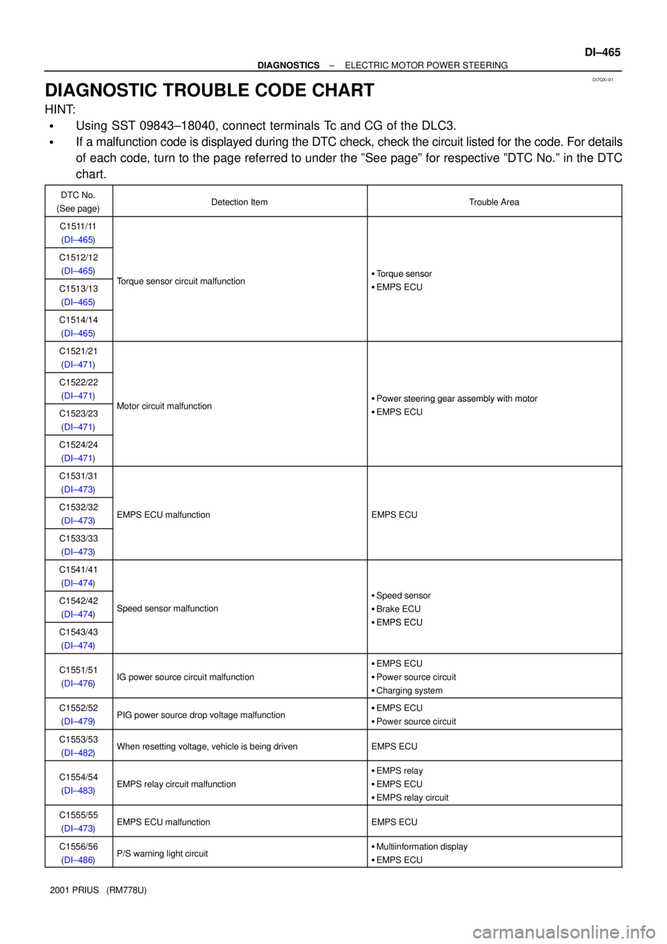
DIAGNOSTIC TROUBLE CODE CHART
HINT:
�Using SST 09843±18040, connect terminals Tc and CG of the DLC3.
�If a malfunction code is displayed during the DTC check, check the circuit listed for the code. For details
of each code, turn to the page referred to under the ºSee pageº for respective ºDTC No.º in the DTC
chart.
DTC No.
(See page)Detection ItemTrouble Area
C1511/11
(DI±465)
C1512/12
(DI±465)
T i it lf ti�Torque sensor
C1513/13
(DI±465)Torque sensor circuit malfunction�Torque sensor
�EMPS ECU
C1514/14
(DI±465)
C1521/21
(DI±471)
C1522/22
(DI±471)
Mt i it lf ti�Power steering gear assembly with motor
C1523/23
(DI±471)Motor circuit malfunction�Power steering gear assembly with motor
�EMPS ECU
C1524/24
(DI±471)
C1531/31
(DI±473)
C1532/32
(DI±473)EMPS ECU malfunctionEMPS ECU
C1533/33
(DI±473)
C1541/41
(DI±474)
C1542/42
(DI±474)Speed sensor malfunction
�Speed sensor
�Brake ECU
�EMPS ECUC1543/43
(DI±474)�EMPS ECU
C1551/51
(DI±476)IG power source circuit malfunction
�EMPS ECU
�Power source circuit
�Charging system
C1552/52
(DI±479)PIG power source drop voltage malfunction�EMPS ECU
�Power source circuit
C1553/53
(DI±482)When resetting voltage, vehicle is being drivenEMPS ECU
C1554/54
(DI±483)EMPS relay circuit malfunction
�EMPS relay
�EMPS ECU
�EMPS relay circuit
C1555/55
(DI±473)EMPS ECU malfunctionEMPS ECU
C1556/56
(DI±486)P/S warning light circuit�Multiinformation display
�EMPS ECU
Page 1049 of 1943
F12837
IDE6
2H
2B
2D5
42 3EMPS ECU
IG
IG S/W
Battery ECU±IG
W
IG B±GB±Y 1
23
6
DC/DC AM1
PGND 5J/C
J15
J14DE
W±B
W±B J11
J/C A
F11 B±Y
W±G B±Y
1 IG1 Relay
2
2I
2K8
F18 FL Block No. 2
FL Block No. 1
F1311
1
2
E5 A J17
J/C Instrument Panel J/B
MAIN
± DIAGNOSTICSELECTRIC MOTOR POWER STEERING
DI±481
2001 PRIUS (RM778U)
DTC C1551/51 IG Power Source Circuit Malfunction
CIRCUIT DESCRIPTION
The EMPS ECU identifies ON or OFF status of ignition switch by this circuit.
DTC No.DTC Detecting ConditionTrouble Area
C1551/51The abnormal IG voltage value which is not within the specifi-
cation is input to EMPS ECU.�EMPS ECU
�Power source circuit
�Charging system
WIRING DIAGRAM
DI7R7±01
Page 1052 of 1943
F12839
PIG
RLY E5
E61
2 B
GR IM1
IA21
7 B
GR 3
3 3
31 35
2 EMPS Relay
R±G B±R
Instrument Panel J/B
ECU±B
6
2G 2H1
W
F111
F101
WFL Block No. 1
DC/DC
F131
Engine Room R/B No. 3
3
321EMPS
FL Block No. 2 F18
MAIN
1
E52
PGND W±B
A J17
J/C
IG BatteryEngine Room R/B No. 3 DI±484
± DIAGNOSTICSELECTRIC MOTOR POWER STEERING
2001 PRIUS (RM778U)
DTC C1552/52 PIG Power Source Circuit
CIRCUIT DESCRIPTION
When turning ignition switch ON, battery voltage is supplied to terminal PIG of EMPS ECU by EMPS relay
operation.
DTC No.DTC Detecting ConditionTrouble Area
C1552/52The abnormal motor power source voltage value which is not
within the specification is input to EMPS ECU.�EMPS ECU
�Power source circuit
WIRING DIAGRAM
DI7R8±01
Page 1055 of 1943
F12839
PIG
RLY E5
E61
2 B
GR IM1
IM21
7 B
GR 3
3 3
31 35
2 EMPS Relay
R±G B±R
Instrument Panel J/B
ECU±B
6
2G
2H1
W
F111
F101
WFL Block No. 1
DC/DC
F131
Engine Room R/B No. 3
3
321EMPS
FL Block No. 2 F18
MAIN
1
E52
PGND W±B
A J17
J/C
IG BatteryEngine Room R/B No. 3 DI±488
± DIAGNOSTICSELECTRIC MOTOR POWER STEERING
2001 PRIUS (RM778U)
DTC C1554/54 EMPS Relay Circuit
CIRCUIT DESCRIPTION
DTC No.DTC Detecting ConditionTrouble Area
C1554/54Open or short circuit is detected.
�EMPS ECU
�EMPS relay
�EMPS relay circuit
WIRING DIAGRAM
DI7RA±01