Page 1056 of 1943
F12828
ON
RLY
PGND
F11788
5
13
2
Open
Continuity
5
2 1
3
5
2 1
3 Continuity
± DIAGNOSTICSELECTRIC MOTOR POWER STEERING
DI±489
2001 PRIUS (RM778U)
INSPECTION PROCEDURE
1 Check voltage between terminals RLY and PGND of EMPS ECU connector.
PREPARATION:
Remove the EMPS ECU with connectors still connected.
CHECK:
Turn the ignition switch ON and measure the voltage between
terminals RLY and PGND of EMPS ECU connector.
OK:
Voltage: 9 ± 14 V
OK Check or replace EMPS ECU.
NG
2 Check EMPS relay.
PREPARATION:
Remove the EMPS relay from the engine room R/B No. 3.
CHECK:
Check the continuity between each terminal of the EMPS relay.
OK:
Terminals 1 and 2Continuity (Reference value 80 W)
Terminals 3 and 5Open
CHECK:
(a) Apply battery positive voltage between terminals 1 and 2.
(b) Check the continuity between the terminals.
OK:
Terminals 3 and 5Continuity
Page 1057 of 1943
F12863
Instrument
Panel J/BECU±B
Fuse
DI±490
± DIAGNOSTICSELECTRIC MOTOR POWER STEERING
2001 PRIUS (RM778U)
NG Replace EMPS relay.
OK
3 Check ECU±B fuse.
PREPARATION:
Remove the ECU±B fuse from instrument panel J/B.
CHECK:
Check the continuity of ECU±B fuse.
OK:
Continuity
NG Check for short in harness and all components
connected to ECU±B fuse (See attached wiring
diagram).
OK
Check for open and short circuit in harness and connector between EMPS ECU and battery
(See page IN±41).
Page 1058 of 1943
F12840
EMPS ECU
WL
E67
Y 3
IP1 L 11 Multiinformation Display
22
L
Instrument Panel J/B
IG1 Relay
3
51
2H GAUGE
2A5
W
FL Block No. 1
1
F11 F131
B±G
1 MAIN FL Block No. 2 F18
BatteryDC/DC
± DIAGNOSTICSELECTRIC MOTOR POWER STEERING
DI±491
2001 PRIUS (RM778U)
DTC C1556/56 P/S Warning Light Circuit
CIRCUIT DESCRIPTION
DTC No.DTC Detecting ConditionTrouble Area
C1556/56There is a malfunction in PS warning light circuit.�Multiinformation display
�EMPS ECU
WIRING DIAGRAM
DI7RB±01
Page 1196 of 1943

H15524
B±W
W5
2BB±O
GR
W±B ACC Relay 10A SRS ACC
5A AM1
FL Block No. 2 FL Block No. 1 15A AM2
Battery 100A
DC/DCB±G W±RA
J11
J/C W±G
W±R P±L1
2H
8
2C2
2E
4
2E
8
2K
2B 536
A18ACC
120A
1 1
F13 1
F12
1
F11 1B9 2
1J B1
2G2
2C ACC
2
67AM1
AM2 IG2MAIN
35
A18IG2 Airbag Sensor
Assembly Instrument Panel J/B
Ignition Switch
ID 12
3
Instrument Panel J/B Engine Room J/B DI±634
± DIAGNOSTICSSUPPLEMENTAL RESTRAINT SYSTEM
2001 PRIUS (RM778U)
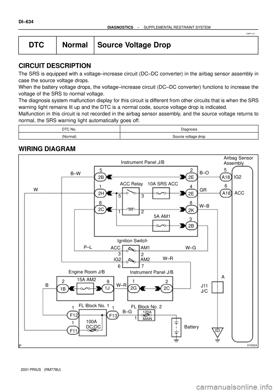
DTC Normal Source Voltage Drop
CIRCUIT DESCRIPTION
The SRS is equipped with a voltage±increase circuit (DC±DC converter) in the airbag sensor assembly in
case the source voltage drops.
When the battery voltage drops, the voltage±increase circuit (DC±DC converter) functions to increase the
voltage of the SRS to normal voltage.
The diagnosis system malfunction display for this circuit is different from other circuits that is when the SRS
warning light remains lit up and the DTC is a normal code, source voltage drop is indicated.
Malfunction in this circuit is not recorded in the airbag sensor assembly, and the source voltage returns to
normal, the SRS warning light automatically goes off.
DTC No.Diagnosis
(Normal)Source voltage drop
WIRING DIAGRAM
DI6PY±07
Page 1199 of 1943
H15525
Combination Meter
Instrument Panel J/B
10A ACC
ACC Relay
5A AM1
W±G L15
C10
16
C10
5
C11
GR±RGR±R
W±BB±Y 9
2A
2
2D
8
2A
1
2H
8
2C
3
2B53
128
2K4
2B 1
2E3
A18LA
1
F11C
J27
Fl Block No. 1
23P±LW 1
F13
1 B±GL
GR±R
BBC
J28AB
A
J11
J/C
Battery F18
FL
Block
No. 2DLC3
DC/DC100A
J/C
I15 Ignition S/W
120A
MAINAirbag Sensor
Assembly
B±Y6
ID J26
J/C
± DIAGNOSTICSSUPPLEMENTAL RESTRAINT SYSTEM
DI±637
2001 PRIUS (RM778U)
SRS Warning Light Circuit Malfunction
CIRCUIT DESCRIPTION
The SRS warning light is located on the combination meter.
When the SRS is normal, the SRS warning light lights up for approx. 6 seconds after the ignition switch is
turned from the LOCK position to ON position, and then turns off automatically.
If there is a malfunction in the SRS, the SRS warning light lights up to inform the driver of the abnormality.
When terminals Tc and CG of the DLC3 are connected, the DTC is displayed by blinking the SRS warning
light.
WIRING DIAGRAM
DI7QT±01
Page 1216 of 1943
I15479
Combination Meter
FL Block No. 1Instrument Panel J/B
to Body ECU 5A AM1IG1
Relay
3
GR±B14
C10
2A
CRUISE 8
W±B
B±G22
C10 L
2K8
2
C11
W±B I15 Ignition SW
AM1
IG1
F11
Battery
ID 10A GAUGE
5
AJ11
J/C 2 1 2B6
2B3
2D6 W
W±G
B±Y
24
B±Y
1F13
1F18
1FL Block No. 2
120A MAIN
100A DC/DC7
2A
1
2H
IH BR
± DIAGNOSTICSCRUISE CONTROL SYSTEM
DI±665
2001 PRIUS (RM778U)
CRUISE MAIN Indicator Light Circuit
CIRCUIT DESCRIPTION
When the cruise control main switch is turned ON, CRUISE MAIN indicator light lights up.
WIRING DIAGRAM
DI7NL±01
Page 1228 of 1943

DI62G±07
DI±688
± DIAGNOSTICSBODY CONTROL SYSTEM
2001 PRIUS (RM778U)
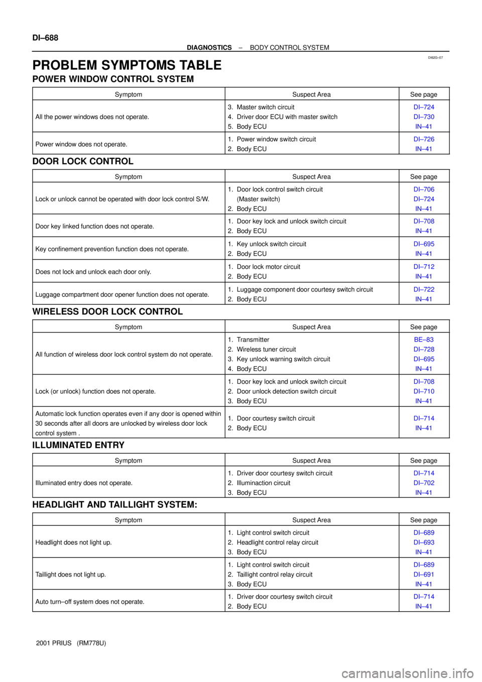
PROBLEM SYMPTOMS TABLE
POWER WINDOW CONTROL SYSTEM
SymptomSuspect AreaSee page
All the power windows does not operate.
3. Master switch circuit
4. Driver door ECU with master switch
5. Body ECUDI±724
DI±730
IN±41
Power window does not operate.1. Power window switch circuit
2. Body ECUDI±726
IN±41
DOOR LOCK CONTROL
SymptomSuspect AreaSee page
Lock or unlock cannot be operated with door lock control S/W.
1. Door lock control switch circuit
(Master switch)
2. Body ECUDI±706
DI±724
IN±41
Door key linked function does not operate.1. Door key lock and unlock switch circuit
2. Body ECUDI±708
IN±41
Key confinement prevention function does not operate.1. Key unlock switch circuit
2. Body ECUDI±695
IN±41
Does not lock and unlock each door only.1. Door lock motor circuit
2. Body ECUDI±712
IN±41
Luggage compartment door opener function does not operate.1. Luggage component door courtesy switch circuit
2. Body ECUDI±722
IN±41
WIRELESS DOOR LOCK CONTROL
SymptomSuspect AreaSee page
All function of wireless door lock control system do not operate.
1. Transmitter
2. Wireless tuner circuit
3. Key unlock warning switch circuit
4. Body ECUBE±83
DI±728
DI±695
IN±41
Lock (or unlock) function does not operate.
1. Door key lock and unlock switch circuit
2. Door unlock detection switch circuit
3. Body ECUDI±708
DI±710
IN±41
Automatic lock function operates even if any door is opened within
30 seconds after all doors are unlocked by wireless door lock
control system .1. Door courtesy switch circuit
2. Body ECUDI±714
IN±41
ILLUMINATED ENTRY
SymptomSuspect AreaSee page
Illuminated entry does not operate.
1. Driver door courtesy switch circuit
2. Illuminaction circuit
3. Body ECUDI±714
DI±702
IN±41
HEADLIGHT AND TAILLIGHT SYSTEM:
SymptomSuspect AreaSee page
Headlight does not light up.
1. Light control switch circuit
2. Headlight control relay circuit
3. Body ECUDI±689
DI±693
IN±41
Taillight does not light up.
1. Light control switch circuit
2. Taillight control relay circuit
3. Body ECUDI±689
DI±691
IN±41
Auto turn±off system does not operate.1. Driver door courtesy switch circuit
2. Body ECUDI±714
IN±41
Page 1230 of 1943
DI6QW±04
I15489
Body ECU
B B9
B8
1 5
8 11
159
8
8
2
13 5 3 1
6
24
1 1BDR F
FJ27
J/C
W±B
W±B
B±GB±Y
W±G W±GWR±G
2C
2D
2K 2B2H
2D10A GAUGE IG1 Relay30A DOOR7.5A ECU±B
5A AM1
J11
J/C
ID Battery F13 F11100A DC/DC FL Block No. 1I15 Ignition Switch
AM1 IG1
F18
FL Block No. 2
120A MAINB9 E Instrument Panel J/B
B
IG
A 7.5A OBDII
9
2DR±G
D
D
J26
J/CW±L W±L
W DI±690
± DIAGNOSTICSBODY CONTROL SYSTEM
2001 PRIUS (RM778U)
CIRCUIT INSPECTION
Power Source Circuit
CIRCUIT DESCRIPTION
This circuit provides power to operate the Body ECU.
WIRING DIAGRAM