Page 1442 of 1943
I18157
ACT(±) (+)
ON
± DIAGNOSTICSAIR CONDITIONING SYSTEM
DI±935
2001 PRIUS (RM778U)
6 Check voltage between terminal ACT of A/C amplifier connector and body
ground.
PREPARATION:
(a) Remove center cluster module control with connector still
connected.
(b) Start the engine and push AUTO switch.
CHECK:
Check the voltage between terminal ACT of A/C amplifier con-
nector and body ground when magnetic clutch is ON and OFF
by A/C switch.
OK:
Magnetic clutchVoltage
ON10 ± 14 V
OFFBelow 1.0 V
NG Check and replace A/C amplifier.
OK
7 Check harness and connector between magnetic clutch relay and A/C amplifier
(See page IN±41).
NG Repair or replace harness or connector.
OK
Proceed to next circuit inspection shown on
problem symptoms table (See page
DI±874).
Page 1443 of 1943
I18381
A/C Amplifier
WP
A93
F18
FL Block No. 2
BatteryInstrument Panel J/BC
R R
2D3 J21A
2D6
2K8 2H1
B±Y HTR
IG1 Relay
AM1
J11
J/C 3
5
2
1
W
A
ID MAIN
FL Block No. 1F111
F131
1DC/DC
B±GA/C W/P Relay
L±R
W2
Water Pump
Motor
A
J1
J/C IG14 2 W±GAM1 2B3
I15 Ignition SWJ20
IE1 13 RJ6
J/C
AA
RREngine Room R/B No. 3
3
33
3 351
2
IE120
L±R
L
1
2 J/C
A
AJ7
J/C W±B
IE DI±936
± DIAGNOSTICSAIR CONDITIONING SYSTEM
2001 PRIUS (RM778U)
Water Pump Circuit
CIRCUIT DESCRIPTION
This is hte power source for the water pump motor.
WIRING DIAGRAM
DI7SN±01
Page 1444 of 1943

I18171
(+) (±)WP ON
Z18060
15 2
3
123 5
± DIAGNOSTICSAIR CONDITIONING SYSTEM
DI±937
2001 PRIUS (RM778U)
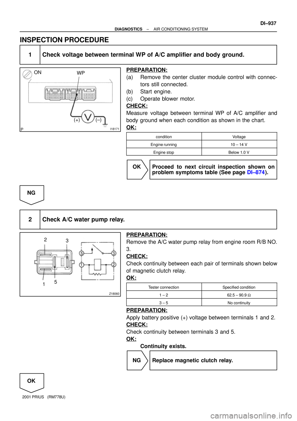
INSPECTION PROCEDURE
1 Check voltage between terminal WP of A/C amplifier and body ground.
PREPARATION:
(a) Remove the center cluster module control with connec-
tors still connected.
(b) Start engine.
(c) Operate blower motor.
CHECK:
Measure voltage between terminal WP of A/C amplifier and
body ground when each condition as shown in the chart.
OK:
conditionVoltage
Engine running10 ± 14 V
Engine stopBelow 1.0 V
OK Proceed to next circuit inspection shown on
problem symptoms table (See page DI±874).
NG
2 Check A/C water pump relay.
PREPARATION:
Remove the A/C water pump relay from engine room R/B NO.
3.
CHECK:
Check continuity between each pair of terminals shown below
of magnetic clutch relay.
OK:
Tester connectionSpecified condition
1 ± 262.5 ± 90.9 W
3 ± 5No continuity
PREPARATION:
Apply battery positive (+) voltage between terminals 1 and 2.
CHECK:
Check continuity between terminals 3 and 5.
OK:
Continuity exists.
NG Replace magnetic clutch relay.
OK
Page 1449 of 1943
DI±942
± DIAGNOSTICSAIR CONDITIONING SYSTEM
2001 PRIUS (RM778U)
PTC Heater Circuit (Quick Heater)
CIRCUIT DESCRIPTION
A/C amplifier switches the HTR3 relay ON by signal from the A/C amplifier. It supplies power to PTC heater
(Quick heater).
DI7SP±01
Page 1450 of 1943
I18386
A8 A8 13
6HTR2
HTR0 A/C Amplifier
P P
IE118
IE116 L±R
P±B
P±B
P±B
L±Y
G±R
1
23
41
2 P2
P2P2
P2P1
P1PTC Heater
W±B
W±B W±B
W±B
W±B
J11
J/CJ1
J/C AA
AA
IE ID IA1
IA1 Engine Room R/B No.3
3
3
3
3
3
3 3
3
3
3
3
3
3
3
3
3HTR3 Relay
HTR2 Relay
HTR1 Relay1
2
5
3
1
2
5
3
1
2
5
3
HTR1
HTR2
HTR3 R±L
G
R±L
G±W
R±L
B±R
W
Instrument Panel J/B
2G
2D
2H
2K 2B8
6
1
8 3GAUGE
IG1 Relay
5 3
21
AM1
B±Y
W±G
24
AM1 IG1 I15
Ignition SW
DC/DCF13
F13 F131
1 1FL Block No.1
F18 FL Block No.2
BatteryMAINW±B
W5
1
± DIAGNOSTICSAIR CONDITIONING SYSTEM
DI±943
2001 PRIUS (RM778U)
WIRING DIAGRAM
Page 1452 of 1943
I18396
Engine Room R/B No. 3
HTR3 Fuse
Z18060
15 2
3
123 5
± DIAGNOSTICSAIR CONDITIONING SYSTEM
DI±945
2001 PRIUS (RM778U)
3 Check HTR3 fuses.
PREPARATION:
Remove the HTR3 fuse from engine room R/B No. 3.
CHECK:
Check continuity of HTR1 and HTR2 fuses.
OK:
Continuity exists.
NG Check for short in all the harness and compo-
nents connected to the HTR1 and HTR2 fuses
(See attached wiring diagram).
OK
4 Check HTR3 relays.
PREPARATION:
Remove the HTR3 relays from engine room relay block No. 3.
CHECK:
Check continuity between each pair of terminals shown below
of magnetic clutch relay.
OK:
Tester connectionSpecified condition
1 ± 262.5 ± 90.9 W
3 ± 5No continuity
PREPARATION:
Apply battery positive (+) voltage between terminals 1 and 2.
CHECK:
Check continuity between terminals 3 and 5.
OK:
Continuity exists.
NG Replace HTR3 relay.
OK
Page 1453 of 1943
I18393
DI±946
± DIAGNOSTICSAIR CONDITIONING SYSTEM
2001 PRIUS (RM778U)
5 Check harness and connector between A/C amplifier and HTR1 and HTR2 fuses
(See page IN±41).
NG Check and replace harness and connector.
OK
Check and replace A/C amplifier.
6 Check PTC heater.
PREPARATION:
Remove the heater radiator (See page AC±51).
CHECK:
Check continuity between terminals of PTC heater connector,
as shown in the chart.
OK:
Tester connectionResult
1 ± 2Continuity
3 ± 4Continuity
NG Replace heater radiator.
OK
Check harness and connector between PTC heater and HTR1, HT2 relays, PTC heater and body
ground (See page IN±41).
Page 1454 of 1943
± DIAGNOSTICSAIR CONDITIONING SYSTEM
DI±947
2001 PRIUS (RM778U)
PTC Heater Circuit (Heater Radiator)
CIRCUIT DESCRIPTION
A/C amplifier switches the HTR1 relay and HTR2 relay ON by signal from the A/C amplifier. It supplies power
to PTC heater (Heater radiator).
DI7SQ±01