Page 1769 of 1943
BE1UY±02
I18844
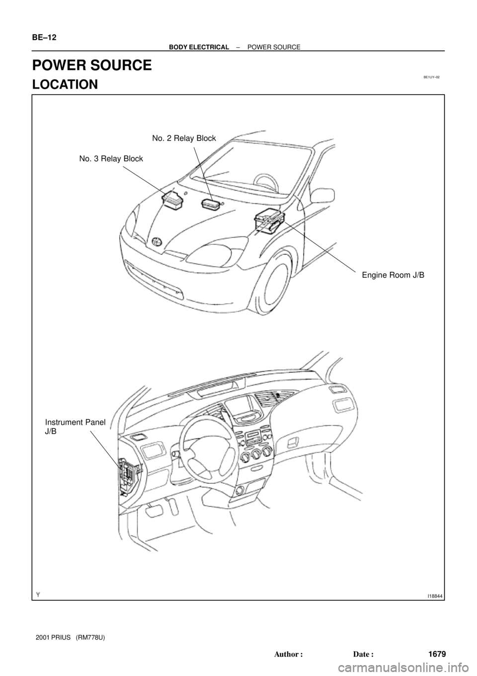
Engine Room J/B No. 2 Relay Block
Instrument Panel
J/B
No. 3 Relay Block BE±12
± BODY ELECTRICALPOWER SOURCE
1679 Author�: Date�:
2001 PRIUS (RM778U)
POWER SOURCE
LOCATION
Page 1770 of 1943
I17787
Engine room J/B:
Fuses:
1. HTR Fuse
2. RDI Fuse
3. ABS No. 2 Fuse
4. CDS FAN Fuse
5. HORN Fuse
6. THRO Fuse
7. ABS No. 3 Fuse
8. TURN±HAZ Fuse
9. AM2 Fuse
10. BATT FANRelays:
A. FAN NO. 1 Relay
B. FAN NO. 2 Relay
C. FAN NO. 3 Relay
D. IG2 Relay
E. HORN Relay
F. HTR Relay
G. EFI Relay
H. CLR MG Relay
I. HEAD Relay
J. CIR OPN Relay
K. DIM Relay *1
123 4 5 6 7 8
91011
121314
1516
17
18 K
J
A B
C D E
F
G H
I
11. DOME Fuse
12. HEAD HI (RH) Fuse *1
13. HEAD HI (LH) Fuse *1
14. HEAD LO (LH) *1
HEAD (LH) *2
15. HEAD LO (RH) *1
HEAD (RH) *2
16. EFI Fuse
17. HEV Fuse
18. HEAD Fuse *1
*1: w/ Daytime Running Light
*2: w/o Daytime Running Light
± BODY ELECTRICALPOWER SOURCE
BE±13
1680 Author�: Date�:
2001 PRIUS (RM778U)
Page 1771 of 1943
I17788
Instrument Panel J/B:
Fuses: Relays:
A. IG1 Relay
B. ACC Relay
C. TAIL Relay
D. POWER Relay
E. DEF Relay
1
2
3
4
5
6
7
8
9
10
11
12
13
14
15 A
B C
D
16
E
1. HTR Fuse
2. STOP Fuse
3. ECU±B Fuse
4. DOOR Fuse
5. OBDII Fuse
6. PWR1 Fuse
7. AM1 Fuse8. GAUGE Fuse
9. ECU±IG Fuse
10. WIPER Fuse
11. WASHER Fuse
12. PANEL Fuse
13. TAIL Fuse
14. ACC Fuse15. CIG Fuse
16. SRS ACC Fuse
17. PWR Fuse
18 DEF Fuse
1718 BE±14
± BODY ELECTRICALPOWER SOURCE
1681 Author�: Date�:
2001 PRIUS (RM778U)
Page 1772 of 1943
I17789
1 2 3456
7 A B
C
D E
Fuses: Relays: Engine Room R/B No. 3:
G H
1. HTR2 Fuse
2. HTR1 Fuse
3. ABS No. 4 Fuse
4. ABS No. 1 Fuse5. EMPS Fuse
6. HTR3 Fuse
7. DRL FuseA. A/C W/P Relay
B. ABS SOL Relay
C. DRL Relay
D. HTR2 RelayE. HTR1 Relay
G. HTR3 Relay
H. EPMS Relay
Engine Room R/B No. 2:
A B C
Relays:
A. IGCT Relay
B. HYDRO MTR No. 2 Relay
C. HYDRO MTR No. 1 Relay
± BODY ELECTRICALPOWER SOURCE
BE±15
1682 Author�: Date�:
2001 PRIUS (RM778U)
Page 1773 of 1943

IN")
BE1UX±02
I14295
7
8
13
14 16
17
HI
Flash OFFTAIL HEAD LO
Z05930
1
2
31
55 3
2
N14863
12
35
12 35
Z05930
1
2
351
2 3
5 BE±20
± BODY ELECTRICALHEADLIGHT AND TAILLIGHT SYSTEM
2001 PRIUS (RM778U)
INSPECTION
1. INSPECT LIGHT CONTROL SWITCH CONTINUITY
Switch positionTester connectionSpecified condition
OFF±No continuity
TAIL14 ± 16Continuity
HEAD13 ± 14 ± 16Continuity
If continuity is not as specified, replace the switch.
2. INSPECT HEADLIGHT DIMMER SWITCH CONTINU-
ITY
Switch positionTester connectionSpecified condition
Low beam16 ± 17Continuity
High beam7 ± 16Continuity
Flash7 ± 8 ± 16Continuity
If continuity is not as specified, replace the switch.
3. INSPECT HEADLIGHT CONTROL RELAY CONTINU-
ITY
ConditionTester connectionSpecified condition
Constant1 ± 3Continuity
Apply B+ between
terminals 1 and 2.2 ± 5Continuity
If continuity is not as specified, replace the relay.
4. INSPECT TAILLIGHT CONTROL RELAY CONTINUITY
ConditionTester connectionSpecified condition
Constant1 ± 2Continuity
Apply B+ between
terminals 1 and 2.3 ± 5Continuity
If continuity is not as specified, replace the relay.
5. INSPECT DRL RELAY CONTINUITY
ConditionTester connectionSpecified condition
Constant1 ± 3Continuity
Apply B+ between
terminals 1 and 2.2 ± 5Continuity
If continuity is not as specified, replace the relay.
Page 1774 of 1943
I17862
Wire Harness Side
h±10±1±A
± BODY ELECTRICALHEADLIGHT AND TAILLIGHT SYSTEM
BE±21
2001 PRIUS (RM778U)
6. INSPECT DAYTIME RUNNING LIGHT MAIN RELAY
CIRCUIT
Disconnect the connector from the relay and inspect the con-
nector on the wire harness side.
Tester connectionConditionSpecified condition
2 ± GroundConstantContinuity
3 ± GroundConstantBattery voltage
4 ± GroundTerminal 5 groundBattery voltage
6 ± GroundConstantBattery voltage
7 ± GroundLight control switch OFF or TAILNo continuity
7 ± GroundLight control switch HEADContinuity
8 ± GroundHeadlight dimmer switch FLASH or HIContinuity
9 ± GroundEngine runningBattery voltage
12 ± GroundIgnition switch OFFNo voltage
12 ± GroundIgnition switch ONBattery voltage
If circuit is specified, try replacing the relay with a new one.
If circuit is not as specified, inspect the circuits connected to oth-
er parts.
Page 1786 of 1943
No. Wiring connector side
1
2
3
10
11
12
13
14
15
16
17
18
19
20
21
22EMPS ECU
Fuel tank temperature (+)
Hybrid vehicle control ECU (4P)
Ground
Ground
Center airbag sensor assembly
Headlight dimmer switch
Turn signal switch (Right)
Turn signal switch (Left)
Fuel tank temperature (±)
DOME Fuse
GAUGE FuseODO/TRIP switch (TC)
ODO/TRIP switch (E)
ODO/TRIP switch (ODO)
9 ABS ECU (SI)
ABS ECU (ABS)
2
3
4
5
6
7 1 Back±up light relay
Body ECU
Engine ECM
ACC Fuse
Light control rheostat (TC)
Light control rheostat (TR) A
BBody ECU
± BODY ELECTRICALCOMBINATION METER
BE±41
2001 PRIUS (RM778U)
Page 1792 of 1943

INSPECTION
1. INSPECT DEFOGGER TIMER OPERATION
(a) Connect the positive (+) lead from")
BE1D5±03
I17792
8 71
I17793
I01200
2 1
35
2 5
1 3
± BODY ELECTRICALDEFOGGER SYSTEM
BE±49
2001 PRIUS (RM778U)
INSPECTION
1. INSPECT DEFOGGER TIMER OPERATION
(a) Connect the positive (+) lead from the battery to terminal
1, 8 and negative (±) lead to terminal 7.
(b) Connect the positive (+) lead from the battery to terminal
5 through a 3.4 W test bulb.
(c) Turn the defogger switch ON and check that the indicator
light and test bulb light up for 12 for 18 minutes, then the
indicator light and test bulb lights go out.
If operation is not as specified, inspect the A/C amplifier.
2. INSPECT DEFOGGER SWITCH CIRCUIT
Connector disconnected:
Disconnect the connector from the switch and inspect the con-
nector on wire harness side, as shown in the chart.
Tester connectionConditionSpecified condition
1 ± GroundIgnition switch LOCK or ACCNo voltage
1 ± GroundIgnition switch ONBattery positive voltage
7 ± GroundConstantContinuity
8 ± GroundConstantBattery positive voltage
If the circuit is not as specified, replace the switch.
3. INSPECT DEFOGGER RELAY CONTINUITY
ConditionTester connectionSpecified condition
Constant1 ± 2Continuity
Apply B+ between
terminals 1 and 2.3 ± 5Continuity
If continuity is not as specified, replace the relay.


6. INSPECT DAYTIME RUNNING LIGHT MAIN RELAY
CIRCUIT
Disconnect the connector from t")

Hybrid vehicle control ECU (4P)
Ground
Ground
Center airbag sensor assembly
Headlight dimmer sw")