Page 1455 of 1943
I18386
A8 A8 13
6HTR2
HTR0 A/C Amplifier
P P
IE118
IE116 L±R
P±B
P±B
P±B
L±Y
G±R
1
23
41
2 P2
P2P2
P2P1
P1PTC Heater
W±B
W±B W±B
W±B
W±B
J11
J/CJ1
J/C AA
AA
IE ID IA1
IA1 Engine Room R/B No.3
3
3
3
3
3
3 3
3
3
3
3
3
3
3
3
3HTR3 Relay
HTR2 Relay
HTR1 Relay1
2
5
3
1
2
5
3
1
2
5
3
HTR1
HTR2
HTR3 R±L
G
R±L
G±W
R±L
B±R
W
Instrument Panel J/B
2G
2D
2H
2K 2B8
6
1
8 3GAUGE
IG1 Relay
5 3
21
AM1
B±Y
W±G
24
AM1 IG1 I15
Ignition SW
DC/DCF13
F13 F131
1 1FL Block No.1
F18 FL Block No.2
BatteryMAINW±B
W5
1 DI±948
± DIAGNOSTICSAIR CONDITIONING SYSTEM
2001 PRIUS (RM778U)
WIRING DIAGRAM
Page 1457 of 1943
I18396
Engine Room R/B No. 3
HTR1 Fuse HTR2 Fuse
Z18060
15 2
3
123 5
DI±950
± DIAGNOSTICSAIR CONDITIONING SYSTEM
2001 PRIUS (RM778U)
3 Check HTR1 and HTR2 fuses.
PREPARATION:
Remove the HTR1 and HTR2 fuses from engine room R/B NO.
3.
CHECK:
Check continuity of HTR1 and HTR2 fuses.
OK:
Continuity exists.
NG Check for short in all the harness and compo-
nents connected to the HTR1 and HTR2 fuses
(See attached wiring diagram).
OK
4 Check HTR1 and HTR2 relays.
PREPARATION:
Remove the HTR1 and HTR2 relays from engine room relay
block NO. 3.
CHECK:
Check continuity between each pair of terminals shown below
of magnetic clutch relay.
OK:
Tester connectionSpecified condition
1 ± 262.5 ± 90.9 W
3 ± 5No continuity
PREPARATION:
Apply battery positive (+) voltage between terminals 1 and 2.
CHECK:
Check continuity between terminals 3 and 5.
OK:
Continuity exists.
NG Replace HTR1 and (or) HTR2 relay.
OK
Page 1458 of 1943
I18395
± DIAGNOSTICSAIR CONDITIONING SYSTEM
DI±951
2001 PRIUS (RM778U)
5 Check harness and connector between A/C amplifier and HTR3 fuse (See page
IN±41).
NG Check and replace harness and connector.
OK
Check and replace A/C amplifier.
6 Check PTC heater (Heater Radiator).
PREPARATION:
Remove the heater radiator (See page AC±27).
CHECK:
Check continuity between terminals of PTC heater connector.
OK:
Continuity exists.
NG Replace heater radiator.
OK
Check harness and connector between PTC heater and HTR3 relay, PTC heater and body ground
(See page IN±41).
Page 1460 of 1943
I18401
A/C Amplifier
CF Engine Room J/B
Fan No.2 Relay
A9
A91
2RF IE16
R±W R±W
1J
1A
1J
1K
1J
1K
1B
1J
1K 1K 10
11
5
3
12
5
2
3
4
7 Fan No.1 Relay
Fan No.1 Relay1
2
5 3
4
1
2
5
3
3 5
12
CDS FAN
RDIV±YJ27
J28J27 EE
E J/C L±W To Engine ECU
W±B
V±Y
From
DC/DC Fuse
From ECU±
IG Fuse 1
1 2 R1 Radiator Fan Motor
W4 Water Temp. Switch12
W±B
W±BA3 A/C Pressure Switch2 3
J1
J/CJ7
J/C
AA A
AW±BW±B
IEV±Y
A1
A/C Condenser
Fan Motor
G±W
W±G
W
L±W2
W±B W±B
± DIAGNOSTICSAIR CONDITIONING SYSTEM
DI±953
2001 PRIUS (RM778U)
WIRING DIAGRAM
Page 1461 of 1943
I18160
ON
(+) (±)CF
RF
Terminal Condition Voltage
10 ± 14 V
Below 1.0 V
Below 1.0 V
10 ± 14 V Water temp.: Below 90°C (194 °F)
Refrigerant pressure:
Below 1,520 kPa (15.5 kgf/cm
2, 220 psi) RF e Body
ground
CF e Body
ground
Water temp.: Above 90°C (194 °F)
Refrigerant pressure:
Above 1,520 kPa (15.5 kgf/cm
2, 220 psi)
A/C switch: ON
A/C switch: OFF
DI±954
± DIAGNOSTICSAIR CONDITIONING SYSTEM
2001 PRIUS (RM778U)
INSPECTION PROCEDURE
1 Check voltage between terminals RF, CF of A/C amplifier and body ground.
PREPARATION:
Remove the center cluster module control with connectors still
connected.
CHECK:
(a) Start engine.
(b) Turn A/C switch ON.
(c) Measure voltage between terminal RF, CF of A/C amplifi-
er and body ground at each conditions as shown in the
chart.
OK:
OK Go to step 4.
NG
2 Check Fan No. 1, No. 2 and No. 3 relays (See page AC±65).
NG Replace faulty relay
OK
Page 1555 of 1943

F12396
TOYOTA Hand±Held Tester
DLC3
SF1KO±01
B11794
7
3
Battery
B11816
B09225
Fuel Tube Connector
SF±6
± SFIFUEL PUMP
1220 Author�: Date�:
2001 PRIUS (RM778U)
FUEL PUMP
ON±VEHICLE INSPECTION
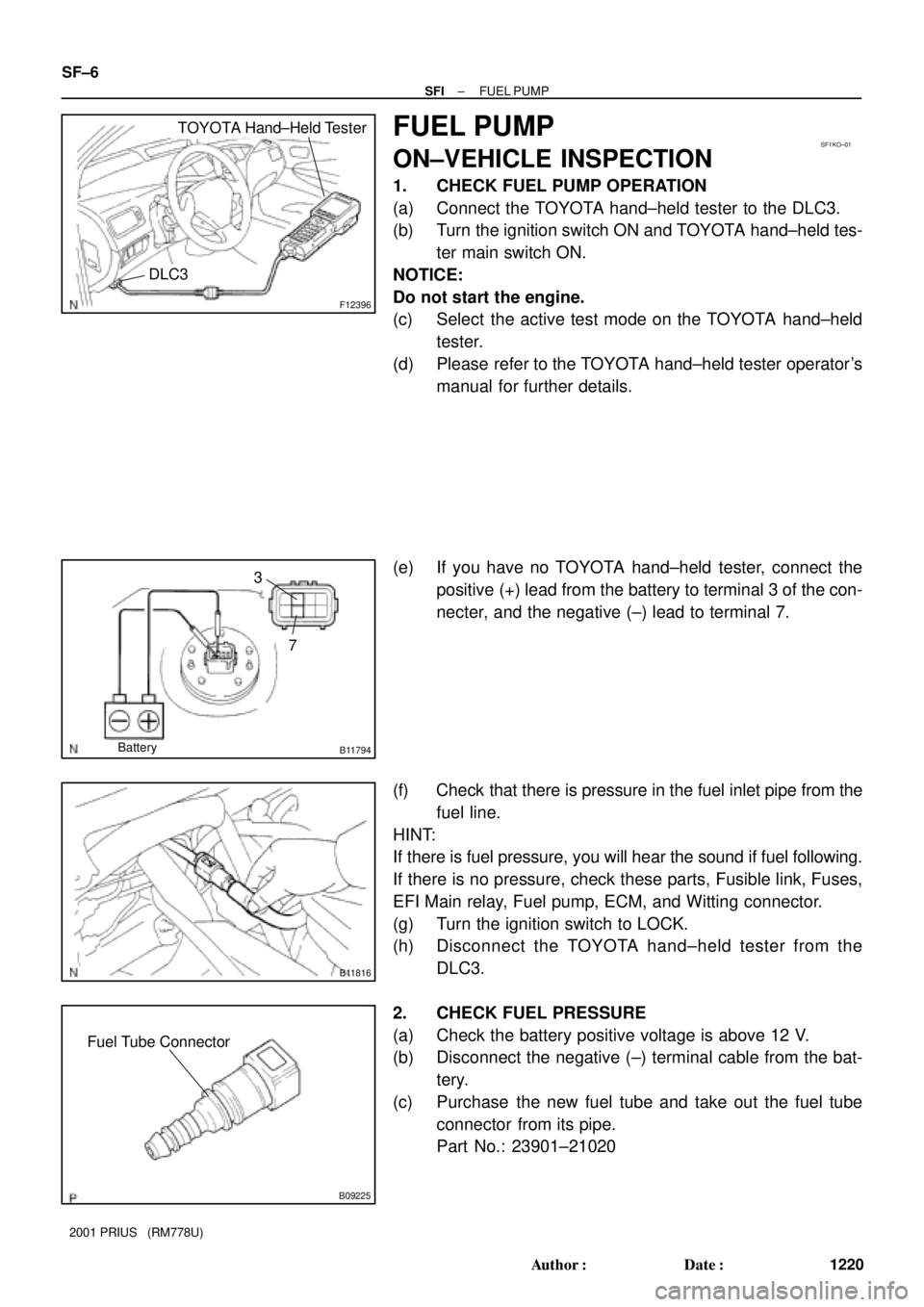
1. CHECK FUEL PUMP OPERATION
(a) Connect the TOYOTA hand±held tester to the DLC3.
(b) Turn the ignition switch ON and TOYOTA hand±held tes-
ter main switch ON.
NOTICE:
Do not start the engine.
(c) Select the active test mode on the TOYOTA hand±held
tester.
(d) Please refer to the TOYOTA hand±held tester operator's
manual for further details.
(e) If you have no TOYOTA hand±held tester, connect the
positive (+) lead from the battery to terminal 3 of the con-
necter, and the negative (±) lead to terminal 7.
(f) Check that there is pressure in the fuel inlet pipe from the
fuel line.
HINT:
If there is fuel pressure, you will hear the sound if fuel following.
If there is no pressure, check these parts, Fusible link, Fuses,
EFI Main relay, Fuel pump, ECM, and Witting connector.
(g) Turn the ignition switch to LOCK.
(h) Disconnect the TOYOTA hand±held tester from the
DLC3.
2. CHECK FUEL PRESSURE
(a) Check the battery positive voltage is above 12 V.
(b) Disconnect the negative (±) terminal cable from the bat-
tery.
(c) Purchase the new fuel tube and take out the fuel tube
connector from its pipe.
Part No.: 23901±21020
Page 1580 of 1943

I18027
No. 1 Cooling
Fan Relay
CO14D±01
B03548No ContinuityContinuity 12 Ohmmeter
5Ohmmeter
3
B03549
Ohmmeter
Continuity1
32
5
Battery
I18027
No. 2 Cooling
Fan Relay
B03550
Continuity
Ohmmeter
No Continuity Continuity4
1
32
Ohmmeter
5
Ohmmeter
± COOLINGCOOLING FAN RELAY
CO±27
1305 Author�: Date�:
2001 PRIUS (RM778U)
COOLING FAN RELAY
INSPECTION
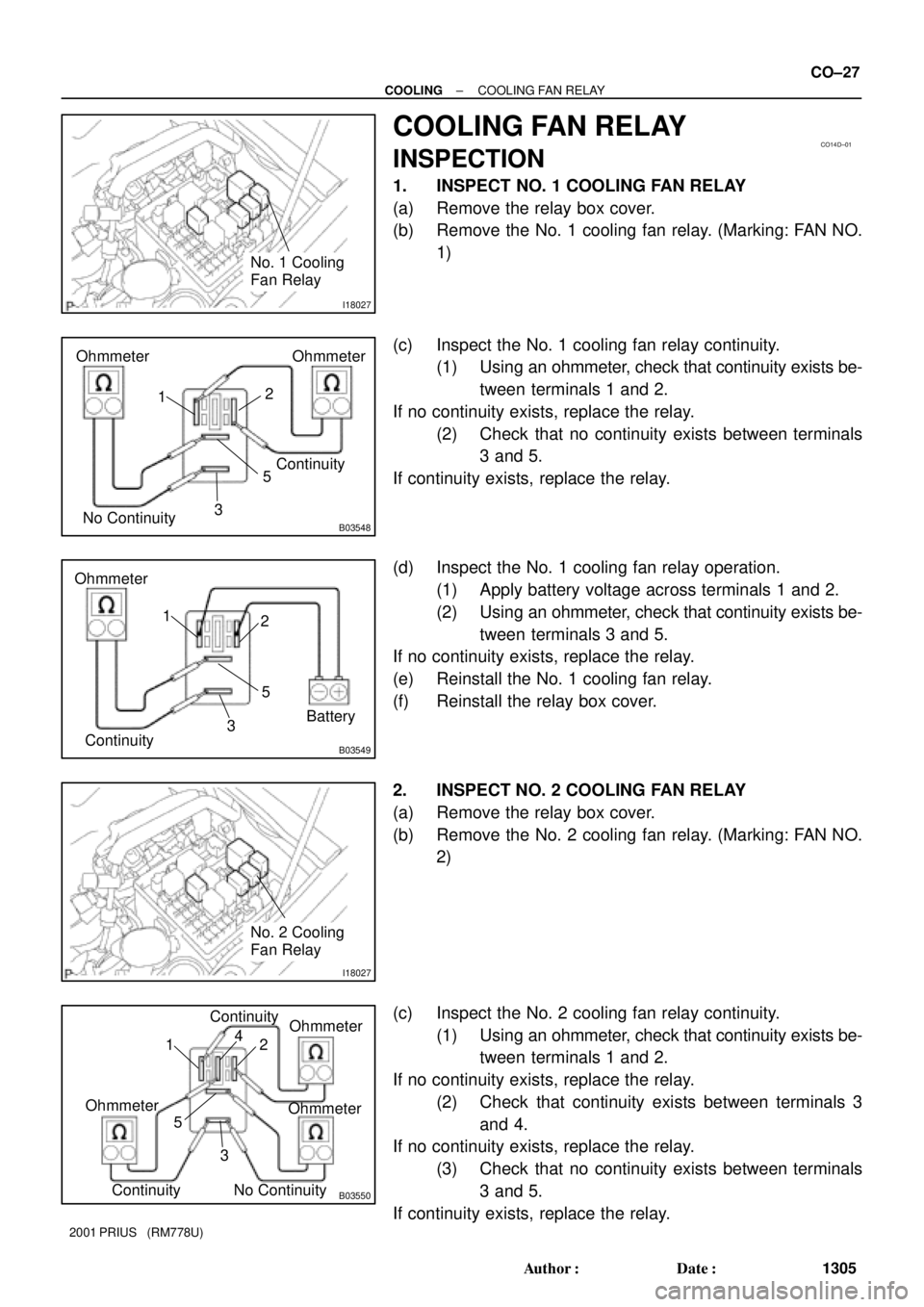
1. INSPECT NO. 1 COOLING FAN RELAY
(a) Remove the relay box cover.
(b) Remove the No. 1 cooling fan relay. (Marking: FAN NO.
1)
(c) Inspect the No. 1 cooling fan relay continuity.
(1) Using an ohmmeter, check that continuity exists be-
tween terminals 1 and 2.
If no continuity exists, replace the relay.
(2) Check that no continuity exists between terminals
3 and 5.
If continuity exists, replace the relay.
(d) Inspect the No. 1 cooling fan relay operation.
(1) Apply battery voltage across terminals 1 and 2.
(2) Using an ohmmeter, check that continuity exists be-
tween terminals 3 and 5.
If no continuity exists, replace the relay.
(e) Reinstall the No. 1 cooling fan relay.
(f) Reinstall the relay box cover.
2. INSPECT NO. 2 COOLING FAN RELAY
(a) Remove the relay box cover.
(b) Remove the No. 2 cooling fan relay. (Marking: FAN NO.
2)
(c) Inspect the No. 2 cooling fan relay continuity.
(1) Using an ohmmeter, check that continuity exists be-
tween terminals 1 and 2.
If no continuity exists, replace the relay.
(2) Check that continuity exists between terminals 3
and 4.
If no continuity exists, replace the relay.
(3) Check that no continuity exists between terminals
3 and 5.
If continuity exists, replace the relay.
Page 1581 of 1943

B03551
Ohmmeter
ContinuityOhmmeter
No Continuity4
1
32
5Battery
I18027
No. 3 Cooling
Fan Relay
B03548
Ohmmeter
No ContinuityOhmmeter
Continuity
5
3 12
B03549
Ohmmeter
Continuity5
3 12
Battery CO±28
± COOLINGCOOLING FAN RELAY
1306 Author�: Date�:
2001 PRIUS (RM778U)
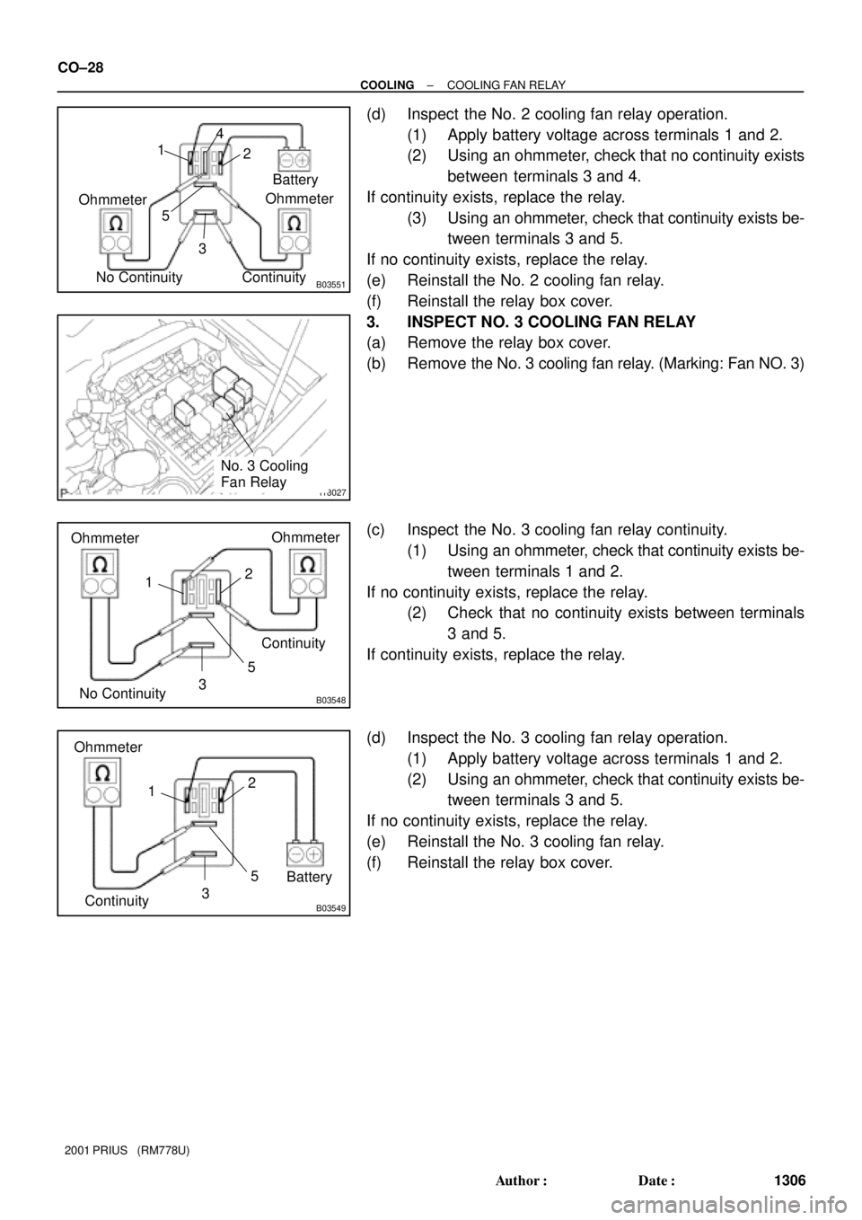
(d) Inspect the No. 2 cooling fan relay operation.
(1) Apply battery voltage across terminals 1 and 2.
(2) Using an ohmmeter, check that no continuity exists
between terminals 3 and 4.
If continuity exists, replace the relay.
(3) Using an ohmmeter, check that continuity exists be-
tween terminals 3 and 5.
If no continuity exists, replace the relay.
(e) Reinstall the No. 2 cooling fan relay.
(f) Reinstall the relay box cover.
3. INSPECT NO. 3 COOLING FAN RELAY
(a) Remove the relay box cover.
(b) Remove the No. 3 cooling fan relay. (Marking: Fan NO. 3)
(c) Inspect the No. 3 cooling fan relay continuity.
(1) Using an ohmmeter, check that continuity exists be-
tween terminals 1 and 2.
If no continuity exists, replace the relay.
(2) Check that no continuity exists between terminals
3 and 5.
If continuity exists, replace the relay.
(d) Inspect the No. 3 cooling fan relay operation.
(1) Apply battery voltage across terminals 1 and 2.
(2) Using an ohmmeter, check that continuity exists be-
tween terminals 3 and 5.
If no continuity exists, replace the relay.
(e) Reinstall the No. 3 cooling fan relay.
(f) Reinstall the relay box cover.