Page 842 of 1943
± DIAGNOSTICSHYBRID VEHICLE CONTROL SYSTEM
DI±251
2001 PRIUS (RM778U)
CIRCUIT DESCRIPTION
If the system main relay is deposited, it might be impossible to shut down the high voltage system. Therefore,
the HV ECU checks the system main relay and stops the system if malfunction is detected.
DTC P3115 ± Information code 231, 232, 233
INF. Code.Detecting ConditionTrouble Area
231System main relay + terminal deposited
232System main relay ± terminal deposited�System main relay
�HV ECU233System main relay + & ± terminal deposited�HV ECU
INSPECTION PROCEDURE
If any of these information codes is output, replace the system main relay.
If one of the information codes above and any of the information codes 224 ± 229 are recorded at the same
time, also replace the HV ECU.
Page 843 of 1943

DI±252
± DIAGNOSTICSHYBRID VEHICLE CONTROL SYSTEM
2001 PRIUS (RM778U)
DTC P3120 HV Transaxle Malfunction
CIRCUIT DESCRIPTION
The HV ECU checks the energy balance and detects abnormality if the magnetism of the motor or generator
greatly decreases.
HINT:
�When using an OBD scan tool other than TOYOTA hand±held tester, check all the steps.
�When using TOYOTA hand±held tester, confirm the information code and check it.
DTC P3120 ± Information code 234, 235, 236, 237
INF. Code.Detecting ConditionTrouble Area
234Small reduction of motor magnetism�HV transaxle (motor)
235Large reduction of motor magnetism
�HV transaxle (motor)
�System main relay
236Small reduction of generator magnetism�HV transaxle (generator)
237Large reduction of generator magnetism
�HV transaxle (generator)
�System main relay
INSPECTION PROCEDURE
1 Is DTC of HV battery ECU being output?
YES Check applicable DTC.
NO
2 Turn the ignition switch to ST(ON) and check if malfunction occurs again.
NO Replace system main relay.
YES
Replace HV transaxle motor or generator.
DI837±02
Page 893 of 1943
A14736
BatteryMAINB±G 1
1
F18 1 1
5
1
F132 3 2
2Engine Room J/B
W±B IK1 2
14
5
AM2 B±WB±W
B±W I15
Ignition SW W±R
6 711
IG2 AM2
Instrument Panel J/B
2C
1K 1A 2G9
1J
1B
B
F12IG2 Relay
Fusible Link
Block No. 1
Fusible Link
Block No. 2 1J
2G
2BW±R
13 3
IE AA AB±W
2
W±B W±B
W±BW3
Water
Pump
Motor
J1
J/C J7
J/C W±B DI±302
± DIAGNOSTICSHYBRID VEHICLE CONTROL SYSTEM
2001 PRIUS (RM778U)
DTC P3130 Inverter Cooling System Malfunction
CIRCUIT DESCRIPTION
The HV ECU checks the operation of the inverter water pump and detects malfunction.
HINT:
�When using an OBD scan tool other than TOYOTA hand±held tester, check all the steps.
�When using TOYOTA hand±held tester, confirm the information code and check it.
DTC P3130 ± Information code 346
INF. code.Detecting ConditionTrouble Area
346Water pump system malfunction
�Inverter water pump
�IG2 relay
�Wire harness
WIRING DIAGRAM
DI839±02
Page 894 of 1943
± DIAGNOSTICSHYBRID VEHICLE CONTROL SYSTEM
DI±303
2001 PRIUS (RM778U)
INSPECTION PROCEDURE
1Check wire harness (See page IN±41).
HINT:
After removing the IG2 relay, check the electrical condition of each terminal.
�No. 1 terminal: With the IG switch ON, 10 ± 14 V
�No. 2 terminal : Continuity between the IG2 relay No. 2 terminal and body ground (less than 1 W )
�No. 3 terminal: Continuity between the IG2 relay No. 3 terminal and water pump No. 2 terminal (less
than 1 W )
�No. 5 terminal: Always 10 ± 14 V
Continuity between the water pump No. 1 terminal and body ground (less than 1 W )
NG Repair or replace wire harness.
OK
Page 895 of 1943

S04947S04946
A14712
Continuity
OhmmeterOhmmeter
No Continuity 2
1
5
3
Ohmmeter
Continuity2
1
5
3
Battery
DI±304
± DIAGNOSTICSHYBRID VEHICLE CONTROL SYSTEM
2001 PRIUS (RM778U)
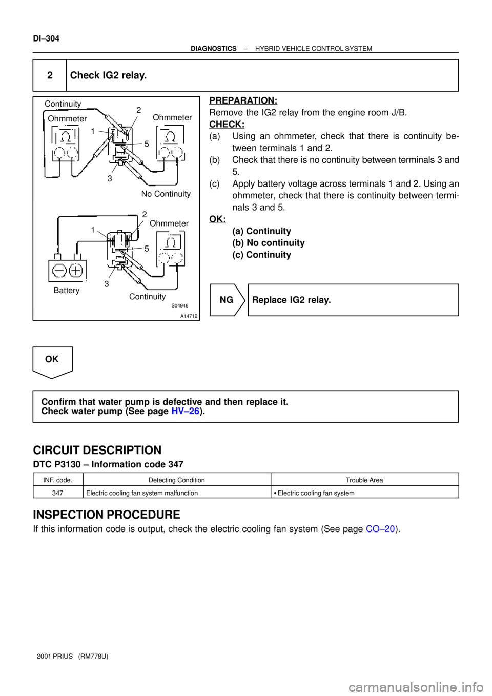
2 Check IG2 relay.
PREPARATION:
Remove the IG2 relay from the engine room J/B.
CHECK:
(a) Using an ohmmeter, check that there is continuity be-
tween terminals 1 and 2.
(b) Check that there is no continuity between terminals 3 and
5.
(c) Apply battery voltage across terminals 1 and 2. Using an
ohmmeter, check that there is continuity between termi-
nals 3 and 5.
OK:
(a) Continuity
(b) No continuity
(c) Continuity
NG Replace IG2 relay.
OK
Confirm that water pump is defective and then replace it.
Check water pump (See page HV±26).
CIRCUIT DESCRIPTION
DTC P3130 ± Information code 347
INF. code.Detecting ConditionTrouble Area
347Electric cooling fan system malfunction�Electric cooling fan system
INSPECTION PROCEDURE
If this information code is output, check the electric cooling fan system (See page CO±20).
Page 898 of 1943
± DIAGNOSTICSHYBRID VEHICLE CONTROL SYSTEM
DI±307
2001 PRIUS (RM778U)
DTC P3140 Interlock Malfunction
CIRCUIT DESCRIPTION
If the HV ECU detects the operation of the safety devices (removal of the service plug, inverter terminal cover
and sensor cover) while the vehicle is not running (with the vehicle is stopped), it will shut down the system
main relay. It the safety devices are correctly installed, it will resume the normal operation after the power
source is supplied again. If it does not, there is a possibility of an open circuit, so perform the same inspection
as the information code 351.
HINT:
�When using an OBD scan tool other than TOYOTA hand±held tester, check all the steps.
�When using TOYOTA hand±held tester, confirm the information code and check it.
DTC P3140 ± Information code 350
INF. code.Detecting ConditionTrouble Area
350Safety devices operating with vehicle is stopped (ILK signal
ON)±
DI83B±02
Page 908 of 1943

F12396
DLC3
TOYOTA hand±held tester
DI±318
± DIAGNOSTICSHV BATTERY CONTROL SYSTEM
2001 PRIUS (RM778U)
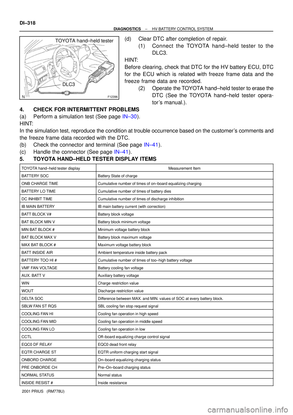
(d) Clear DTC after completion of repair.
(1) Connect the TOYOTA hand±held tester to the
DLC3.
HINT:
Before clearing, check that DTC for the HV battery ECU, DTC
for the ECU which is related with freeze frame data and the
freeze frame data are recorded.
(2) Operate the TOYOTA hand±held tester to erase the
DTC (See the TOYOTA hand±held tester opera-
tor 's manual.).
4. CHECK FOR INTERMITTENT PROBLEMS
(a) Perform a simulation test (See page IN±30).
HINT:
In the simulation test, reproduce the condition at trouble occurrence based on the customer's comments and
the freeze frame data recorded with the DTC.
(b) Check the connector and terminal (See page IN±41).
(c) Handle the connector (See page IN±41).
5. TOYOTA HAND±HELD TESTER DISPLAY ITEMS
TOYOTA hand±held tester displayMeasurement Item
BATTERY SOCBattery State of charge
ONB CHARGE TIMECumulative number of times of on±board equalizing charging
BATTERY LO TIMECumulative number of times of battery dies
DC INHIBIT TIMECumulative number of times of discharge inhibition
IB MAIN BATTERYIB main battery current (with correction)
BATT BLOCK V#Battery block voltage
BAT BLOCK MIN VBattery block minimum voltage
MIN BAT BLOCK #Minimum voltage battery block
BAT BLOCK MAX VBattery block maximum voltage
MAX BAT BLOCK #Maximum voltage battery block
BATT INSIDE AIRAmbient temperature inside battery pack
BATTERY TOO HI #Cumulative number of times of too±high battery voltage
VMF FAN VOLTAGEBattery cooling fan voltage
AUX. BATT VAuxiliary battery voltage
WINCharge restriction value
WOUTDischarge restriction value
DELTA SOCDifference between MAX. and MIN. values of SOC at every battery block.
SBLW FAN ST RQSSBL cooling fan stop request signal
COOLING FAN HICooling fan operation in high speed
COOLING FAN MIDCooling fan operation in middle speed
COOLING FAN LOCooling fan operation in low
CCTLOff±board equalizing charge control signal
EQC0 DF RELAYEQC0 dead front relay
EQTR CHARGE STEQTR uniform charging start signal
ONBORD CHARGEOn±board equalizing charging status
PRE ONBORDE CHPre±On±board charging status
NORMAL STATUSNormal status
INSIDE RESIST #Inside resistance
Page 912 of 1943
A15624
HV ECUBattery ECU
HTD+
HTD±W
B 2
H13
20
H13W
B 1
IF2
2
IF26
B17
7
B17 DI±326
± DIAGNOSTICSHV BATTERY CONTROL SYSTEM
2001 PRIUS (RM778U)
DTC P3002 HV ECU Communication Malfunction
CIRCUIT DESCRIPTION
The battery ECU receives information of the AC ECU, system main relay connection signals, etc. sent from
the HV ECU, and stores DTC when an error is detected in the receives information.
DTC No.DTC Detecting ConditionTrouble Area
P3002No serial signals transmitted from HV ECU�Communication bus line
�HV ECU
HINT:
Check DTC of other ECUs and see whether any communication error of the HV ECU is stored or not.
If HV communication errors are stored in then one ECU, replace the HV ECU.
WIRING DIAGRAM
DI826±01