Page 649 of 1943
A14052
ECM
G±R
7
236 1B1AIA2 12
BR
G±Y 1
1 EFI2
1 5
11
1 1
12
3 Engine Room J/B
B±GF12
MAINFL
Block
No. 2
BatteryJ1
J/C W±B4
B
P±L
Y12
2
4 3
A
IEB
IP1BR
J23 BR
H9
Bank 1
Sensor 22
1 4
3
18
E10
E10E2 MREL
E11
BR IE1
IE1
IE1 W
W
D
11 2225
16
7 (Shielded) (Shielded)(Shielded) 2
FL Block No. 1
F13
J7
J/CJ4
J/C
J/C
A
ACHT1A
OX1B E10E10 E10E8E9
OX1A
HT1B G±R
EFI
Relay
1K 1F
1F
C
B
J23 J22 J23E
E EBR BR IK1
IK1
IK1 W (Shielded)P±L
P±L H3
Bank 1
Sensor 1
B
B
W±B 3
13
12
± DIAGNOSTICSENGINE
DI±45
2001 PRIUS (RM778U)
HINT:
After confirming DTC P0125, use the OBD II scan tool or TOYOTA hand-held tester to confirm voltage output
of oxygen sensor (bank 1 sensor 1) from "CURRENT DATA".
If voltage output of oxygen sensor (bank 1 sensor 1) is less than 0.1 V, oxygen sensor (bank 1 sensor 1) circuit
may be open or short.
WIRING DIAGRAM
Page 661 of 1943
A13626
ON
HT1A
(+) (±) HT1B
DI±58
± DIAGNOSTICSENGINE
2001 PRIUS (RM778U)
1 Check voltage between terminals HT1A, HT1B of ECM connectors and body
ground.
PREPARATION:
(a) Remove the ECM with connector still connected (See
page SF±62).
(b) Turn the ignition switch ON.
CHECK:
Measure voltage between terminals HT1A, HT1B of ECM con-
nectors and body ground.
HINT:
�Connect terminal HT1A to bank 1 sensor 1.
�Connect terminal HT1B to bank 1 sensor 2.
OK:
Voltage: 9 ± 14 V
OK Check and replace ECM (See page IN±41).
NG
2 Check resistance of heated oxygen sensor heater (See page SF±58).
NG Replace heated oxygen sensor.
OK
Check and repair harness or connector between EFI relay (Marking: EFI), heated oxygen sensor
and ECM (See page IN±41).
Page 669 of 1943
A14053
Battery F13 A
B 1K
1 AM2 Engine RoomJ/B
W±R
71 1A
1E5
6Instrument
Panel J/B65
B±R
IG2
B±GR±W
B±W B±W
B±W
B±WI5
Injector No. 1
1
2C1
21
2
1 2
J1
J/C
B±W
L±W
1 9
2G
2BE8
E8
E7
E7Engine ECU
#10
#20
#30
#40 Y
11 3
I15
Ignition SW W±B1J
12
F12 A
MAIN
I6
Injector No. 2
I7
Injector No. 3
I8
Injector No. 4
1J
1B
AM2
A3
2G2
2
2
J7
J/C
B±W
B±W
B±W
B±WB±W
W±R
IG2
Relay
2 2
1 3
5
1 W±BFL Block No. 1
F18 FL Block No. 2 DI±66
± DIAGNOSTICSENGINE
2001 PRIUS (RM778U)
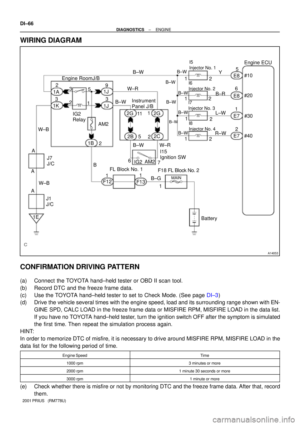
WIRING DIAGRAM
CONFIRMATION DRIVING PATTERN
(a) Connect the TOYOTA hand±held tester or OBD II scan tool.
(b) Record DTC and the freeze frame data.
(c) Use the TOYOTA hand±held tester to set to Check Mode. (See page DI±3)
(d) Drive the vehicle several times with the engine speed, load and its surrounding range shown with EN-
GINE SPD, CALC LOAD in the freeze frame data or MISFIRE RPM, MISFIRE LOAD in the data list.
If you have no TOYOTA hand±held tester, turn the ignition switch OFF after the symptom is simulated
the first time. Then repeat the simulation process again.
HINT:
In order to memorize DTC of misfire, it is necessary to drive around MISFIRE RPM, MISFIRE LOAD in the
data list for the following period of time.
Engine SpeedTime
1000 rpm3 minutes or more
2000 rpm1 minute 30 seconds or more
3000 rpm1 minute or more
(e) Check whether there is misfire or not by monitoring DTC and the freeze frame data. After that, record
them.
Page 685 of 1943
A14054
11 1A 6
1K
BR 3
1BG±R
1
2 CAIA2
32E9ECM
CCV EVP1
E2
PTNK
VC E7
LE925
2
15V2 VSV
(EVAP)4
TBP Engine Room J/B
B±R 1
1 11F
1 1EFI
Relay
3
2
112
6 B EFI
W±B
BC1
V5 VSV (Purge Flow
Switching Valve) B±G
IE A F12
MAIN
Battery1 5
7 B
BB
C B
4 3
5
2
13
1 1F13
F13
J1
J/CJ7
J/C
A AW±BMREL
29
E9
E8
E9
E818
22 G±R
J/C
J5 J4
IA1 BB19
J4J5 J5J/C
V4
Vapor Pressure
Sensor
Y±RJ8
J/C
Y±R
BC1 BC1 BC1
BC1 BC1BC1
IO1
2
2
2 V6 VSV (Canister Closed Valve)
B
C Y±R
Y±R L±R L±RBRL B±R B CA
AB
R±L
FL Block No. 1
F18
FL Block No. 2 DI±82
± DIAGNOSTICSENGINE
2001 PRIUS (RM778U)
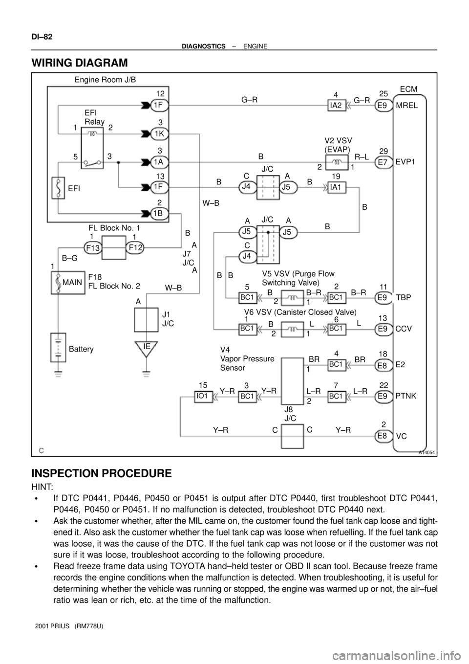
WIRING DIAGRAM
INSPECTION PROCEDURE
HINT:
�If DTC P0441, P0446, P0450 or P0451 is output after DTC P0440, first troubleshoot DTC P0441,
P0446, P0450 or P0451. If no malfunction is detected, troubleshoot DTC P0440 next.
�Ask the customer whether, after the MIL came on, the customer found the fuel tank cap loose and tight-
ened it. Also ask the customer whether the fuel tank cap was loose when refuelling. If the fuel tank cap
was loose, it was the cause of the DTC. If the fuel tank cap was not loose or if the customer was not
sure if it was loose, troubleshoot according to the following procedure.
�Read freeze frame data using TOYOTA hand±held tester or OBD II scan tool. Because freeze frame
records the engine conditions when the malfunction is detected. When troubleshooting, it is useful for
determining whether the vehicle was running or stopped, the engine was warmed up or not, the air±fuel
ratio was lean or rich, etc. at the time of the malfunction.
Page 695 of 1943
DI±92
± DIAGNOSTICSENGINE
2001 PRIUS (RM778U)
14 Check vacuum hose between intake manifold and VSV for EVAP, and VSV for
EVAP and charcoal canister.
CHECK:
(a) Check that the vacuum hose is connected correctly.
(b) Check the vacuum hose for looseness and disconnection.
(c) Check the vacuum hose for cracks, hole, damage and blockage.
NG Repair or replace.
OK
15 Check operation of VSV for EVAP (See page SF±40).
OK Go to step 16.
NG
Replace VSV and charcoal canister,and then clean the vacuum hose between throttle body and
VSV for EVAP, and VSV for EVAP and charcoal canister.
16 Check for open and short in harness and connector between EFI main relay
(Marking: EFI) and VSV for EVAP, and VSV for EVAP and ECM (See page
IN±41).
NG Repair or replace harness or connector.
OK
Check and replace ECM (See page IN±41).
Page 697 of 1943
A14464
VSV is ONVSV is OFF
Air FilterAir Filter
FE
F E
DI±94
± DIAGNOSTICSENGINE
2001 PRIUS (RM778U)
Replace VSV and charcoal canister, and then clean vacuum hose between charcoal canister and
VSV for CCV.
20 Check for open and short in harness and connector between EFI main relay
(Marking: EFI) and VSV for CCV, and VSV for CCV and ECM (See page IN±41).
NG Repair or replace harness or connector.
OK
Check and replace ECM (See page IN±41).
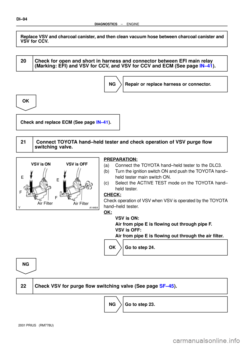
21 Connect TOYOTA hand±held tester and check operation of VSV purge flow
switching valve.
PREPARATION:
(a) Connect the TOYOTA hand±held tester to the DLC3.
(b) Turn the ignition switch ON and push the TOYOTA hand±
held tester main switch ON.
(c) Select the ACTIVE TEST mode on the TOYOTA hand±
held tester.
CHECK:
Check operation of VSV when VSV is operated by the TOYOTA
hand±held tester.
OK:
VSV is ON:
Air from pipe E is flowing out through pipe F.
VSV is OFF:
Air from pipe E is flowing out through the air filter.
OK Go to step 24.
NG
22 Check VSV for purge flow switching valve (See page SF±45).
NG Go to step 23.
Page 698 of 1943
BE6653A10620A14040A14045
START
ON
OFFVSV for EVAP
1.2 V ON
OFF
E2
PTNK
(±) (+)
VSV for CCV
Measure
Voltage30 sec.
± DIAGNOSTICSENGINE
DI±95
2001 PRIUS (RM778U)
OK
Replace VSV and charcoal canister, and clean vacuum hoses ((1), (2) and (3) in Fig. 1 in circuit
description.
23 Check for open and short in harness and connector between EFI main relay
(Marking: EFI) and VSV for purge flow switching valve, and VSV for purge flow
switching valve and ECU (See page IN±41).
NG Repair or replace harness or connector.
OK
Check and replace ECM (See page IN±41).
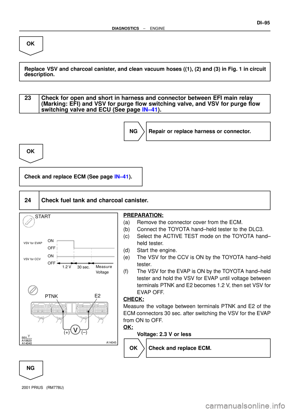
24 Check fuel tank and charcoal canister.
PREPARATION:
(a) Remove the connector cover from the ECM.
(b) Connect the TOYOTA hand±held tester to the DLC3.
(c) Select the ACTIVE TEST mode on the TOYOTA hand±
held tester.
(d) Start the engine.
(e) The VSV for the CCV is ON by the TOYOTA hand±held
tester.
(f) The VSV for the EVAP is ON by the TOYOTA hand±held
tester and hold the VSV for EVAP until voltage between
terminals PTNK and E2 becomes 1.2 V, then set VSV for
EVAP OFF.
CHECK:
Measure the voltage between terminals PTNK and E2 of the
ECM connectors 30 sec. after switching the VSV for the EVAP
from ON to OFF.
OK:
Voltage: 2.3 V or less
OK Check and replace ECM.
NG
Page 702 of 1943
BE6653
A12550A14041A14046
ON
F
F E
E VSV is ONVSV is OFF
VSV is ON
VSV is OFF
EVP1
± DIAGNOSTICSENGINE
DI±99
2001 PRIUS (RM778U)
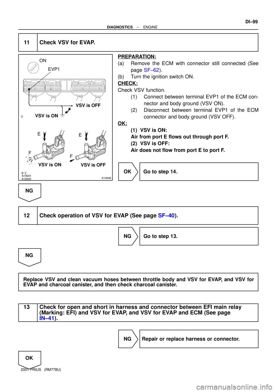
11 Check VSV for EVAP.
PREPARATION:
(a) Remove the ECM with connector still connected (See
page SF±62).
(b) Turn the ignition switch ON.
CHECK:
Check VSV function.
(1) Connect between terminal EVP1 of the ECM con-
nector and body ground (VSV ON).
(2) Disconnect between terminal EVP1 of the ECM
connector and body ground (VSV OFF).
OK:
(1) VSV is ON:
Air from port E flows out through port F.
(2) VSV is OFF:
Air does not flow from port E to port F.
OK Go to step 14.
NG
12 Check operation of VSV for EVAP (See page SF±40).
NG Go to step 13.
NG
Replace VSV and clean vacuum hoses between throttle body and VSV for EVAP, and VSV for
EVAP and charcoal canister, and then check charcoal canister.
13 Check for open and short in harness and connector between EFI main relay
(Marking: EFI) and VSV for EVAP, and VSV for EVAP and ECM (See page
IN±41).
NG Repair or replace harness or connector.
OK