Page 1615 of 2572

Injection volume
Output voltage
Output voltage of heated oxygen
sensor (sensor 2)Ma")
+25 %
-12.5 %
More than 3.35 V
Less than 3.0 V
Case 1
Case 2
Case 3
Case 4
Output voltage of A/F sensor
(sensor 1)
Injection volume
Output voltage
Output voltage of heated oxygen
sensor (sensor 2)Main suspect
trouble area
OK
+25 %
-12.5 %
More than 3.35 V
Less than 3.0V
Injection volume
Output voltage
+25 %
-12.5 %
More than 0.55 V
Less than 0.4V
Injection volume
Output voltage
A/F sensor
(A/F sensor, heater, A/F sen-
sor circuit)
+25 %
-12.5 %
More than 0.55 V
Less than 0.4V
Injection volume
Output voltage
+25 %
-12.5 %
Injection volume
Output voltage
NG
+25 %
-12.5 %
Injection volume
Output voltage
NG
+25 %
-12.5 %
Injection volume
Output voltage
NG
+25 %
-12.5 %
Injection volume
Output voltage
NGExtremely rich or lean actual
air-fuel ratio
(Injector, fuel pressure, gas
leakage in exhaust system,
etc.) OK
OK
OK
Almost
No reaction
Almost
No reaction
Almost
No reaction Almost
No reaction
'
Heated oxygen sensor
(heated oxygen sensor,
heater, heated oxygen sensor
circuit) 05-304
- DIAGNOSTICSSFI SYSTEM (2AZ-FE)
494 Author�: Date�:
2005 HIGHLANDER REPAIR MANUAL (RM1144U)
(a) Perform the ACTIVE TEST A/F CONTROL operation.
HINT:
The A/F CONTROL operation lowers the injection volume by 12.5% or increases the injection volume by
25%.
(1) Connect the hand-held tester to the DLC3 on the vehicle.
(2) Turn the ignition switch ON.
(3) Warm up the engine by running the engine at 2,500 rpm for approximately 90 seconds.
(4) Enter the following menus: DIAGNOSIS / ENHANCED OBD II / ACTIVE TEST / A/F CONTROL.
(5) Perform the A/F CONTROL operation with the engine idling (press the right or left button).
Result:
A/F sensor reacts in accordance with increase and decrease of injection volume:
+25 % " RICH output: Less than 3.0 V
-12.5 % " LEAN output: More than 3.35 V
Heated oxygen sensor reacts in accordance with increase and decrease of injection volume:
+25 % " RICH output: More than 0.55 V
-12.5 % " LEAN output: Less than 0.4 V
NOTICE:
The A/F sensor output has a few seconds of delay and the heated oxygen sensor output has about
20 seconds of delay at maximum.
The following A/F CONTROL procedure enables a technician to check and graph the voltage outputs of both
the A/F sensor and the heated oxygen sensor.
Page 1616 of 2572

05-305
495 Author�: Date�:
2005 HIGHLANDER REPAIR MANUAL (RM1144U)
For displaying the graph, enter ºACTIVE TEST / A/F CONTROL / USER DATAº, select ºAFS B1S1 and O")
- DIAGNOSTICSSFI SYSTEM (2AZ-FE)
05-305
495 Author�: Date�:
2005 HIGHLANDER REPAIR MANUAL (RM1144U)
For displaying the graph, enter ºACTIVE TEST / A/F CONTROL / USER DATAº, select ºAFS B1S1 and O2S
B1S2º by pressing ºYESº and push ºENTERº. Then press ºF4º.
HINT:
�DTC P2A00 may be also detected, when the air fuel ratio is stuck rich or lean.
�A low A/F sensor voltage could be caused by a RICH air-fuel mixture. Check for conditions that would
cause the engine to run with a RICH air-fuel mixture.
�A high A/F sensor voltage could be caused by a LEAN air-fuel mixture. Check for conditions that would
cause the engine to run with a LEAN air-fuel mixture.
�Read freeze frame data using the hand-held tester or the OBD II scan tool. Freeze frame data records
the engine conditions when a malfunction is detected. When troubleshooting, freeze frame data can
help determine if the vehicle was running or stopped, if the engine was warmed up or not, if the air-fuel
ratio was lean or rich, and other data from the time the malfunction occurred.
1 CHECK OTHER DTC OUTPUT (IN ADDITION TO A/F SENSOR DTC)
(a) Read the DTC using the hand-held tester or the OBD II scan tool.
Result:
DisplayProceed to
Only P2A00 is outputA
P2A00 and other codes is outputB
HINT:
If any other codes besides P2A00 is output, perform the troubleshoot on that DTC before.
B GO TO RELEVANT DTC CHART
(See page 05-48)
A
2 READ VALUE OF OBD II SCAN TOOL OR HAND-HELD TESTER (OUTPUT VOLT-
AGE OF A/F SENSOR)
(a) Connect the hand-held tester or the OBD II scan tool to the DLC3.
(b) Warm up the A/F sensor (bank 1 sensor 1) by running the engine at 2,500 rpm for approximately 90
seconds.
(c) Read the A/F sensor voltage output on the the hand-held tester or OBD II scan tool.
(d) Hand-held tester only:
On the hand-held tester, enter the following menus: DIAGNOSIS / ENHANCED OBD II / SNAPSHOT
/ MANUAL SNAPSHOT / USER DATA. Read the values.
(e) Select ºAFS B1 S1
/ ENGINE SPDº and press YES.
(f) Monitor the A/F sensor voltage carefully.
(g) Check the A/F sensor voltage output under the following conditions:
(1) Allow the engine to idle for 30 seconds.
(2) Run the engine at approximately 2,500 rpm. Do not suddenly change the rpm.
(3) Raise the engine speed to 4,000 rpm and quickly release the accelerator pedal so that the throttle
is fully closed.
Page 1617 of 2572
 Idle (2) Approximately 2,500 rpm
Fuel Cut
When A/F sensor circuit is malfunctioning,
voltage output does not change A/F
Sensor
Voltage A/F
Sensor
Voltage
(1) Idl")
A72304
Engine
RPMEngine
RPM (1) Idle (2) Approximately 2,500 rpm
Fuel Cut
When A/F sensor circuit is malfunctioning,
voltage output does not change A/F
Sensor
Voltage A/F
Sensor
Voltage
(1) Idle
Fuel Cut (3) Approximately 4,000 rpm
ºCondition (1), (2)º
Change of approximately 3.3 V Normal Condition
Malfunction Condition
ºCondition (3)º
3.8 V or More(1) Idle (2) Approximately 2,500 rpm(3) Approximately 4,000 rpm
(1) Idle
05-306
- DIAGNOSTICSSFI SYSTEM (2AZ-FE)
496 Author�: Date�:
2005 HIGHLANDER REPAIR MANUAL (RM1144U)
Standard:
Condition (1) and (2)
Voltage change of 3.3 V (0.66 V)* (between approximately 3.1 to 3.5 V) as shown in the illustra-
tion.
Condition (3)
A/F sensor voltage increases to 3.8 V (0.76 V)* or more when fuel is cut during engine decelera-
tion as shown in the illustration.
*: Voltage when using the OBD II scan tool.
HINT:
�Whenever the A/F sensor output voltage remains at approximately 3.3 V (0.660 V)* (see ºMalfunction
Conditionº graphic) under any condition as well as the above conditions, the A/F sensor may have an
open circuit. This will happen also when the A/F sensor heater has an open circuit.
�Whenever the A/F sensor output voltage remains at a certain value of approximately 3.8 V (0.76 V)*
or more, or 2.8 V (0.56 V)* or less (see ºMalfunction Conditionº graphic) under any condition as well
as the above conditions, the A/F sensor may have a short circuit.
�The ECM will stop fuel injection (fuel is cut) during engine deceleration. This will cause a LEAN condi-
tion and should result in a momentary increase in the A/F sensor output voltage.
�The ECM must establish a closed throttle position learned value to perform fuel cut. If the battery termi-
nal has been disconnected, the vehicle must be driven over 10 mph (16 km/h) to allow the ECM to learn
the closed throttle position.
�When the vehicle is driven:
The output voltage of the A/F sensor may be below 2.8 V (0.76 V)* during fuel enrichment. For the
vehicle, this translates to a sudden increase in speed with the accelerator pedal fully depressed when
trying to overtake another vehicle. The A/F sensor is functioning normally.
�The A/F sensor is a current output element, and therefore the current is converted into voltage inside
the ECM. If measuring voltage at connectors of the A/F sensor or ECM, you will observe a constant
voltage.
*: Voltage when using the OBD II scan tool.
OK Go to step 14
Page 1618 of 2572
A52607
AF-AF+
A6
A/F sensor
B60778
5
12 312
5
3
- DIAGNOSTICSSFI SYSTEM (2AZ-FE)
05-307
497 Author�: Date�:
2005 HIGHLANDER REPAIR MANUAL (RM1144U)
NG
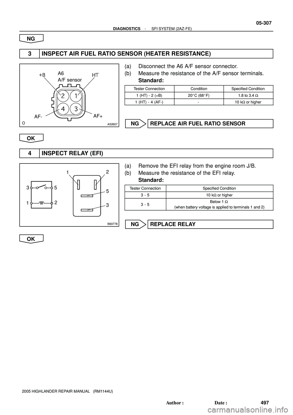
3 INSPECT AIR FUEL RATIO SENSOR (HEATER RESISTANCE)
(a) Disconnect the A6 A/F sensor connector.
(b) Measure the resistance of the A/F sensor terminals.
Standard:
Tester ConnectionConditionSpecified Condition
1 (HT) - 2 (+B)20�C (68�F)1.8 to 3.4 W
1 (HT) - 4 (AF-)-10 kW or higher
NG REPLACE AIR FUEL RATIO SENSOR
OK
4 INSPECT RELAY (EFI)
(a) Remove the EFI relay from the engine room J/B.
(b) Measure the resistance of the EFI relay.
Standard:
Tester ConnectionSpecified Condition
3 - 510 kW or higher
3 - 5Below 1 W
(when battery voltage is applied to terminals 1 and 2)
NG REPLACE RELAY
OK
Page 1619 of 2572

12
34
A76787
A81695A86849
Wire Harness Side
A6
A/F Sensor
HT
+B
E8
ECM
HA1A
AF+AF-
A1A-A1A+
A90346
A/F Sensor
EFI Relay
Heater
Sensor
A1A+ HA1A
Duty
Control ECM
From
Battery
A1A-
MREL Reference
+B
AF-AF+ HT
EFI NO. 1
FuseEFI NO. 2
Fuse
05-308
- DIAGNOSTICSSFI SYSTEM (2AZ-FE)
498 Author�: Date�:
2005 HIGHLANDER REPAIR MANUAL (RM1144U)
5 CHECK WIRE HARNESS (A/F SENSOR - ECM)
(a) Check the wire harness between the ECM and A/F sen-
sor.
(1) Disconnect the A6 A/F sensor connector.
(2) Disconnect the E8 ECM connector.
(3) Measure the resistance of the wire harness side
connectors.
Standard:
Tester ConnectionSpecified Condition
A6-3 (AF+) - E8-23 (A1A+)
A6-4 (AF-) - E8-31 (A1A-)
A6-1 (HT) - E8-5 (HA1A)
Below 1 W
A6-3 (AF+) or A1A+ (E8-23) - Body ground
A6-4 (AF-) or A1A- (E8-31) - Body ground
A6-1 (HT) or HA1A (E8-5) - Body ground
10 kW or higher
NG REPAIR OR REPLACE HARNESS AND
CONNECTOR
OK
6 CHECK AIR INDUCTION SYSTEM
(a) Check for vacuum leaks in the air induction system.
OK: There is no leak in the air induction system.
NG REPAIR OR REPLACE AIR INDUCTION SYSTEM
OK
Page 1620 of 2572
- DIAGNOSTICSSFI SYSTEM (2AZ-FE)
05-309
499 Author�: Date�:
2005 HIGHLANDER REPAIR MANUAL (RM1144U)
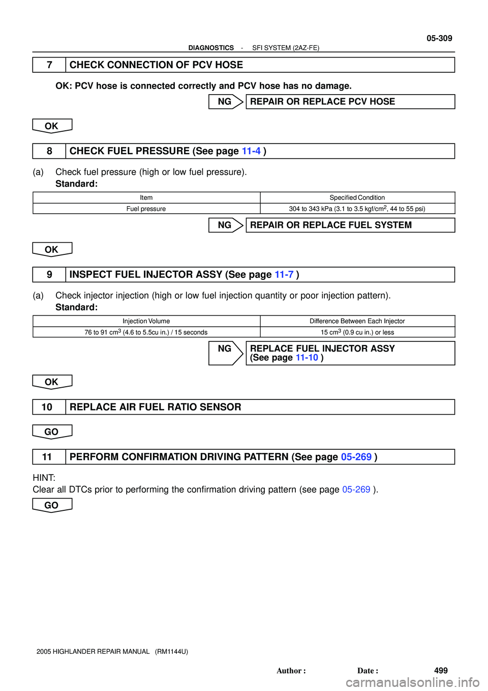
7 CHECK CONNECTION OF PCV HOSE
OK: PCV hose is connected correctly and PCV hose has no damage.
NG REPAIR OR REPLACE PCV HOSE
OK
8 CHECK FUEL PRESSURE (See page 11-4)
(a) Check fuel pressure (high or low fuel pressure).
Standard:
ItemSpecified Condition
Fuel pressure304 to 343 kPa (3.1 to 3.5 kgf/cm2, 44 to 55 psi)
NG REPAIR OR REPLACE FUEL SYSTEM
OK
9 INSPECT FUEL INJECTOR ASSY (See page 11-7)
(a) Check injector injection (high or low fuel injection quantity or poor injection pattern).
Standard:
Injection VolumeDifference Between Each Injector
76 to 91 cm3 (4.6 to 5.5cu in.) / 15 seconds15 cm3 (0.9 cu in.) or less
NG REPLACE FUEL INJECTOR ASSY
(See page 11-10)
OK
10 REPLACE AIR FUEL RATIO SENSOR
GO
11 PERFORM CONFIRMATION DRIVING PATTERN (See page 05-269)
HINT:
Clear all DTCs prior to performing the confirmation driving pattern (see page 05-269).
GO
Page 1621 of 2572
05-310
- DIAGNOSTICSSFI SYSTEM (2AZ-FE)
500 Author�: Date�:
2005 HIGHLANDER REPAIR MANUAL (RM1144U)
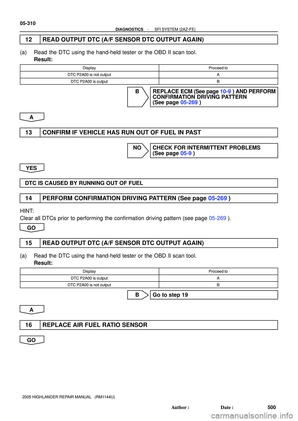
12 READ OUTPUT DTC (A/F SENSOR DTC OUTPUT AGAIN)
(a) Read the DTC using the hand-held tester or the OBD II scan tool.
Result:
DisplayProceed to
DTC P2A00 is not outputA
DTC P2A00 is outputB
B REPLACE ECM (See page 10-9) AND PERFORM
CONFIRMATION DRIVING PATTERN
(See page 05-269)
A
13 CONFIRM IF VEHICLE HAS RUN OUT OF FUEL IN PAST
NO CHECK FOR INTERMITTENT PROBLEMS
(See page 05-9)
YES
DTC IS CAUSED BY RUNNING OUT OF FUEL
14 PERFORM CONFIRMATION DRIVING PATTERN (See page 05-269)
HINT:
Clear all DTCs prior to performing the confirmation driving pattern (see page 05-269).
GO
15 READ OUTPUT DTC (A/F SENSOR DTC OUTPUT AGAIN)
(a) Read the DTC using the hand-held tester or the OBD II scan tool.
Result:
DisplayProceed to
DTC P2A00 is outputA
DTC P2A00 is not outputB
B Go to step 19
A
16 REPLACE AIR FUEL RATIO SENSOR
GO
Page 1622 of 2572
- DIAGNOSTICSSFI SYSTEM (2AZ-FE)
05-31 1
501 Author�: Date�:
2005 HIGHLANDER REPAIR MANUAL (RM1144U)
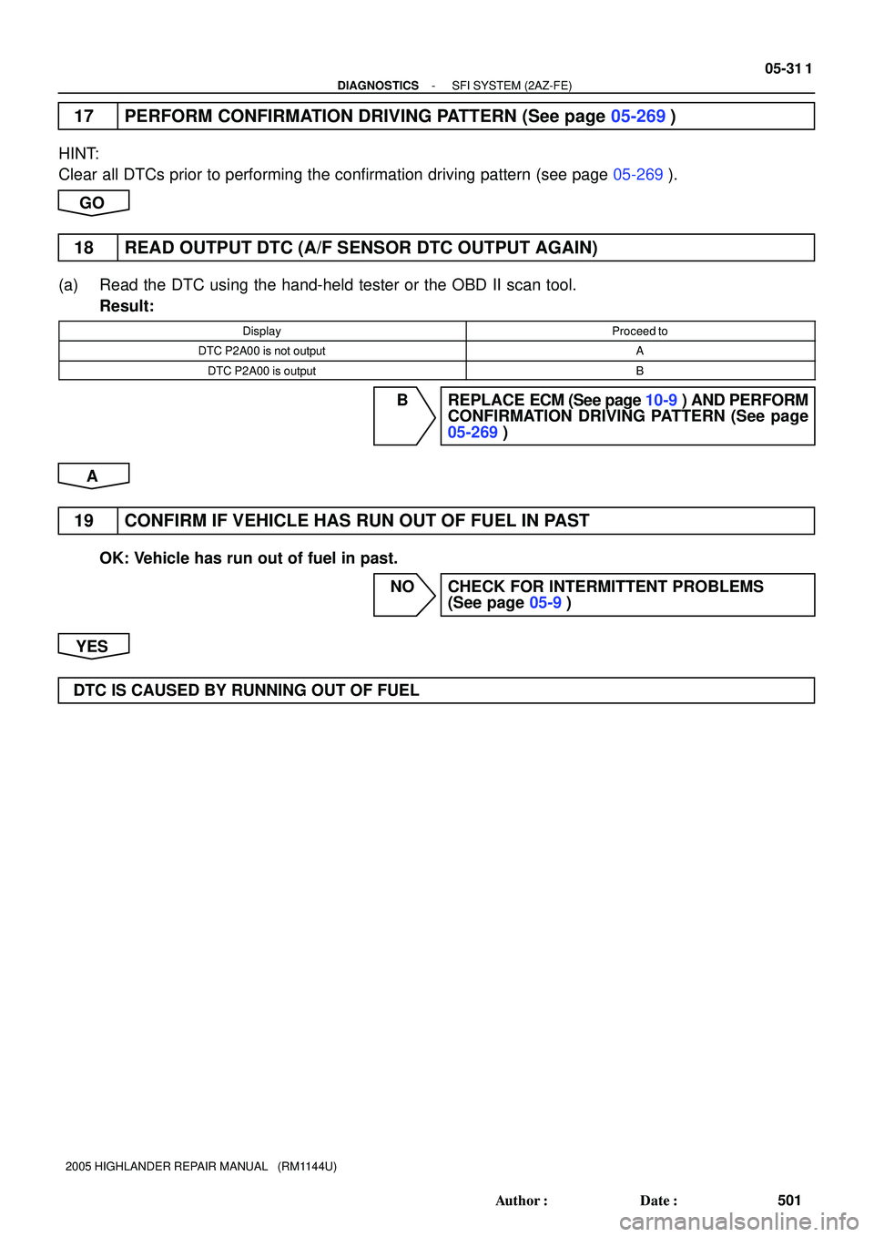
17 PERFORM CONFIRMATION DRIVING PATTERN (See page 05-269)
HINT:
Clear all DTCs prior to performing the confirmation driving pattern (see page 05-269).
GO
18 READ OUTPUT DTC (A/F SENSOR DTC OUTPUT AGAIN)
(a) Read the DTC using the hand-held tester or the OBD II scan tool.
Result:
DisplayProceed to
DTC P2A00 is not outputA
DTC P2A00 is outputB
B REPLACE ECM (See page 10-9) AND PERFORM
CONFIRMATION DRIVING PATTERN (See page
05-269)
A
19 CONFIRM IF VEHICLE HAS RUN OUT OF FUEL IN PAST
OK: Vehicle has run out of fuel in past.
NO CHECK FOR INTERMITTENT PROBLEMS
(See page 05-9)
YES
DTC IS CAUSED BY RUNNING OUT OF FUEL