Page 1524 of 2572
A92558
05-18
- DIAGNOSTICSSFI SYSTEM (2AZ-FE)
208 Author�: Date�:
2005 HIGHLANDER REPAIR MANUAL (RM1144U)
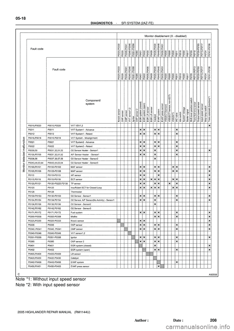
Note *1: Without input speed sensor
Note *2: With input speed sensor
Page 1525 of 2572
A92559
- DIAGNOSTICSSFI SYSTEM (2AZ-FE)
05-19
209 Author�: Date�:
2005 HIGHLANDER REPAIR MANUAL (RM1144U)
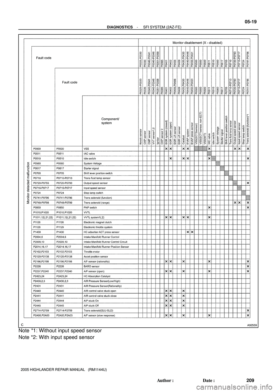
Note *1: Without input speed sensor
Note *2: With input speed sensor
Page 1526 of 2572
A92560
05-20
- DIAGNOSTICSSFI SYSTEM (2AZ-FE)
210 Author�: Date�:
2005 HIGHLANDER REPAIR MANUAL (RM1144U)
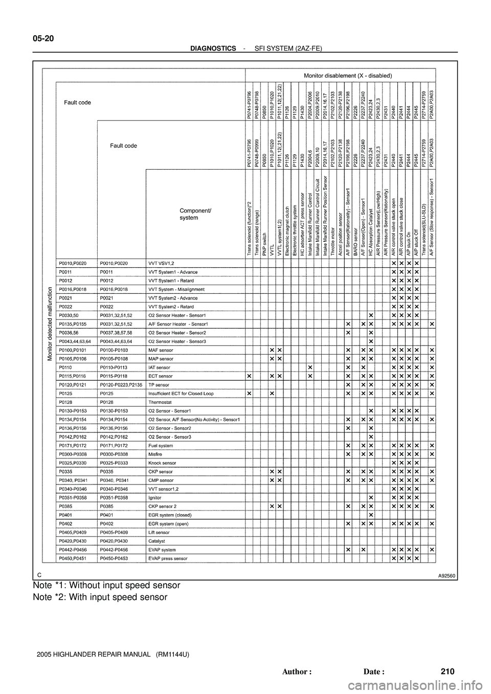
Note *1: Without input speed sensor
Note *2: With input speed sensor
Page 1527 of 2572
A92561
- DIAGNOSTICSSFI SYSTEM (2AZ-FE)
05-21
211 Author�: Date�:
2005 HIGHLANDER REPAIR MANUAL (RM1144U)
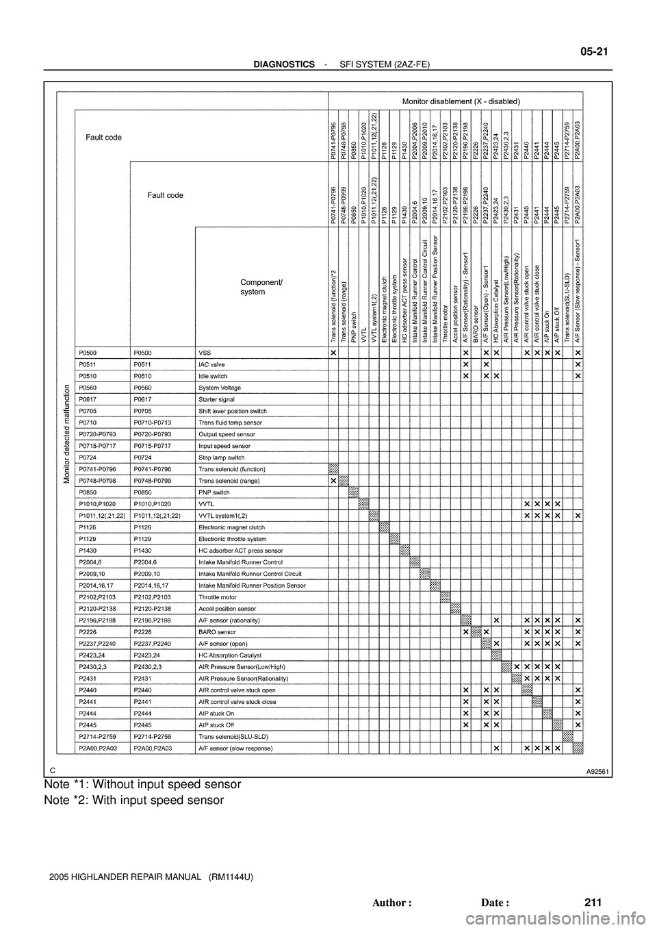
Note *1: Without input speed sensor
Note *2: With input speed sensor
Page 1545 of 2572
E68822E70389
4
3
1 A23
Automatic Light Control Sensor
21
20
12 B9
B9
B9CLTS
CLTE
CLTB R
W
GBody ECU
CLTS
CLTE
CLTB
- DIAGNOSTICSLIGHTING SYSTEM
05-1589
1779 Author�: Date�:
2005 HIGHLANDER REPAIR MANUAL (RM1144U)
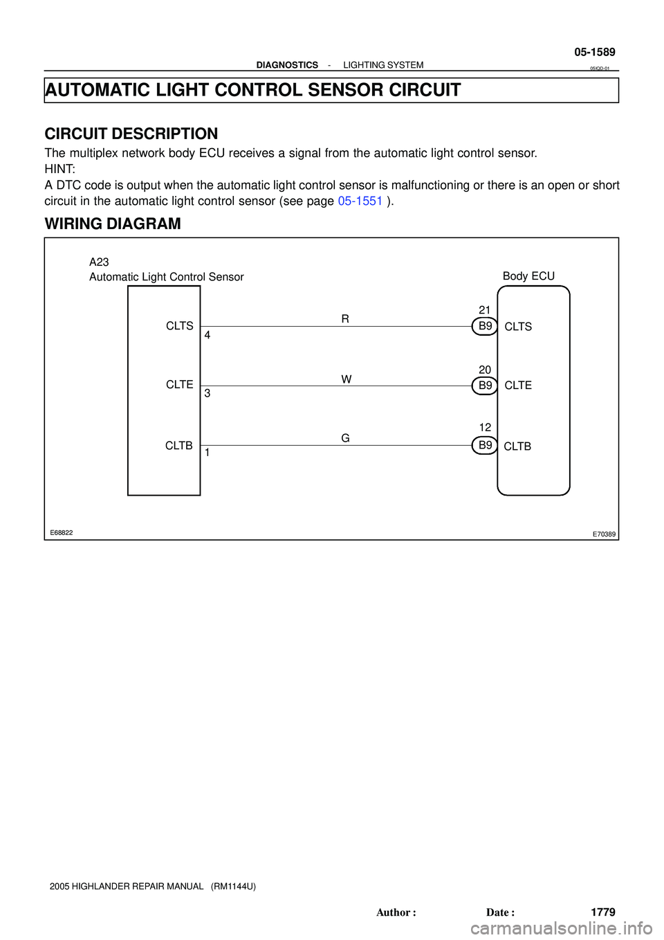
AUTOMATIC LIGHT CONTROL SENSOR CIRCUIT
CIRCUIT DESCRIPTION
The multiplex network body ECU receives a signal from the automatic light control sensor.
HINT:
A DTC code is output when the automatic light control sensor is malfunctioning or there is an open or short
circuit in the automatic light control sensor (see page 05-1551).
WIRING DIAGRAM
05IQD-01
Page 1546 of 2572

I39976
Wire Harness View:
Automatic Light Control Sensor
A23
1
3
I39976
Wire Harness View:
Automatic Light Control Sensor
A23
4
E74263
Multiplex Network Body ECU
Connector Front View:
B9
B9-21
05-1590
- DIAGNOSTICSLIGHTING SYSTEM
1780 Author�: Date�:
2005 HIGHLANDER REPAIR MANUAL (RM1144U)
INSPECTION PROCEDURE
1 CHECK HARNESS AND CONNECTOR(AUTOMATIC LIGHT CONTROL SENSOR
POWER SOURCE CIRCUIT)
(a) Disconnect the automatic light control sensor connector.
(b) Measure the voltage according to the value(s) in the table
below.
Standard:
Tester connectionConditionSpecified condition
A23-1 - A23-3Ignition switch ON10 to 14 V
NG Go to step 4
OK
2 CHECK HARNESS AND CONNECTOR(MULTIPLEX NETWORK BODY ECU -
AUTOMATIC LIGHT CONTROL SENSOR)
(a) Disconnect the B9 connector from the multiplex network
body ECU.
(b) Measure the resistance according to the value(s) in the
table below.
Standard:
Tester connectionConditionSpecified condition
A23-4 - B9-21AlwaysBelow 1 W
NG REPAIR OR REPLACE HARNESS OR
CONNECTOR
OK
Page 1547 of 2572
I39976
Wire Harness View:
Automatic Light Control Sensor
A23
1
- DIAGNOSTICSLIGHTING SYSTEM
05-1591
1781 Author�: Date�:
2005 HIGHLANDER REPAIR MANUAL (RM1144U)
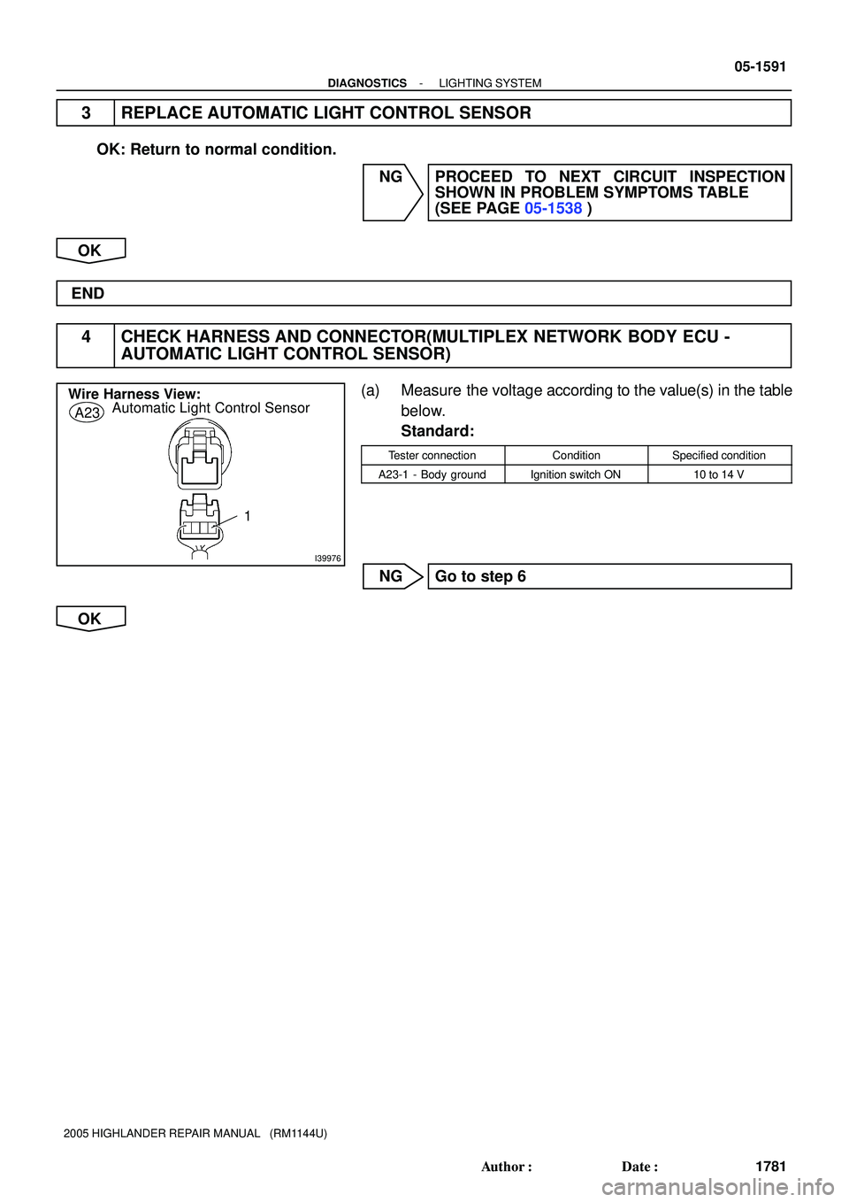
3 REPLACE AUTOMATIC LIGHT CONTROL SENSOR
OK: Return to normal condition.
NG PROCEED TO NEXT CIRCUIT INSPECTION
SHOWN IN PROBLEM SYMPTOMS TABLE
(SEE PAGE 05-1538)
OK
END
4 CHECK HARNESS AND CONNECTOR(MULTIPLEX NETWORK BODY ECU -
AUTOMATIC LIGHT CONTROL SENSOR)
(a) Measure the voltage according to the value(s) in the table
below.
Standard:
Tester connectionConditionSpecified condition
A23-1 - Body groundIgnition switch ON10 to 14 V
NG Go to step 6
OK
Page 1548 of 2572
I39976
Wire Harness View:
Automatic Light Control Sensor
A23
3
E74263
Multiplex Network Body ECU
Connector Front View:
B9
B9-20
05-1592
- DIAGNOSTICSLIGHTING SYSTEM
1782 Author�: Date�:
2005 HIGHLANDER REPAIR MANUAL (RM1144U)
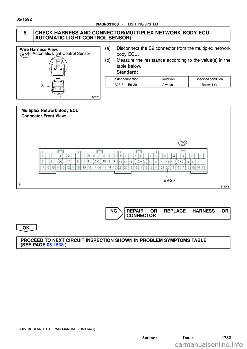
5 CHECK HARNESS AND CONNECTOR(MULTIPLEX NETWORK BODY ECU -
AUTOMATIC LIGHT CONTROL SENSOR)
(a) Disconnect the B9 connector from the multiplex network
body ECU.
(b) Measure the resistance according to the value(s) in the
table below.
Standard:
Tester connectionConditionSpecified condition
A23-3 - B9-20AlwaysBelow 1 W
NG REPAIR OR REPLACE HARNESS OR
CONNECTOR
OK
PROCEED TO NEXT CIRCUIT INSPECTION SHOWN IN PROBLEM SYMPTOMS TABLE
(SEE PAGE 05-1538)