Page 1597 of 2572
I39192
Multi-display AssyNavigation ECU
R N4 W2
M424
R
7
3
1
8
6
2827 23 26 25
M4
M4
M4
M4
M4N4
N4
N4
N4
N4G
B
VR
SYNC
VG R
G
B
Y
Shielded G
B
VR
SYNC
VG 05-1852
- DIAGNOSTICSNAVIGATION SYSTEM
2042 Author�: Date�:
2005 HIGHLANDER REPAIR MANUAL (RM1144U)
DISPLAY SIGNAL CIRCUIT (NAVIGATION ECU - MULTI-DISPLA Y)
CIRCUIT DESCRIPTION
This is the display signal circuit from the navigation ECU to the multi-display.
WIRING DIAGRAM
05IT4-02
Page 1598 of 2572

INSPECTION PROCE")
I40183
Navigation ECU:
N4
BR
VR
VG
G SYNC
I38998R
M4 Multi-Display:
SYNC
G BVR VG
- DIAGNOSTICSNAVIGATION SYSTEM
05-1853
2043 Author�: Date�:
2005 HIGHLANDER REPAIR MANUAL (RM1144U)
INSPECTION PROCEDURE
1 CHECK HARNESS AND CONNECTOR(NAVIGATION ECU - MULTI-DISPLA Y)
(a) Disconnect the connector from the navigation ECU N4
and multi-display M4.
(b) Measure the resistance according to the value(s) in the
table below.
Standard:
Tester connectionConditionSpecified condition
R (N4) - R (M4)AlwaysBelow 1 W
G (N4) - G (M4)AlwaysBelow 1 W
B (N4) - B (M4)AlwaysBelow 1 W
SYNC (N4) - SYNC (M4)AlwaysBelow 1 W
VR (N4) - VR (M4)AlwaysBelow 1 W
VG (N4) - VG (M4)AlwaysBelow 1 W
R (N4 or M4) -
Body groundAlways10 kW or higher
G (N4 or M4) -
Body groundAlways10 kW or higher
B (N4 or M4) -
Body groundAlways10 kW or higher
SYNC (N4 or M4) -
Body groundAlways10 kW or higher
VR (N4 or M4) -
Body groundAlways10 kW or higher
VG (N4 or M4) -
Body groundAlways10 kW or higher
NG REPAIR OR REPLACE HARNESS OR
CONNECTOR
OK
PROCEED TO NEXT CIRCUIT INSPECTION SHOWN ON PROBLEM SYMPTOMS TABLE
(SEE PAGE 05-1778)
Page 1599 of 2572
I39190
Multi-displayNavigation ECU
TX+
TX- BR SB
TX1+
TX1-
M35 M34
N45
N410 05-1860
- DIAGNOSTICSNAVIGATION SYSTEM
2050 Author�: Date�:
2005 HIGHLANDER REPAIR MANUAL (RM1144U)
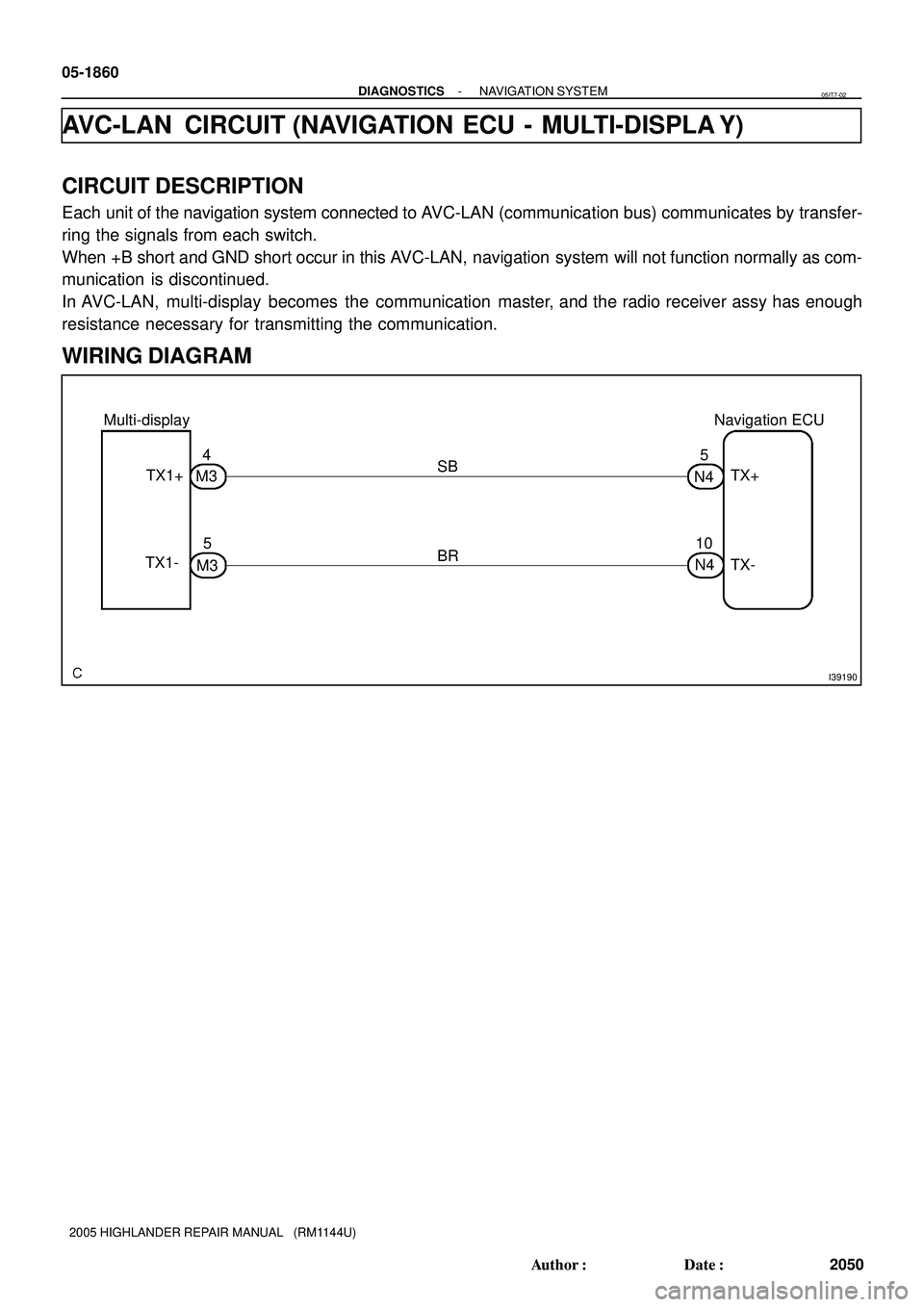
AVC-LAN CIRCUIT (NAVIGATION ECU - MULTI-DISPLA Y)
CIRCUIT DESCRIPTION
Each unit of the navigation system connected to AVC-LAN (communication bus) communicates by transfer-
ring the signals from each switch.
When +B short and GND short occur in this AVC-LAN, navigation system will not function normally as com-
munication is discontinued.
In AVC-LAN, multi-display becomes the communication master, and the radio receiver assy has enough
resistance necessary for transmitting the communication.
WIRING DIAGRAM
05IT7-02
Page 1600 of 2572
I40183
Navigation ECU:
TX+
TX-N4
I38678
Multi-Display:
TX1- TX1+M3
- DIAGNOSTICSNAVIGATION SYSTEM
05-1861
2051 Author�: Date�:
2005 HIGHLANDER REPAIR MANUAL (RM1144U)
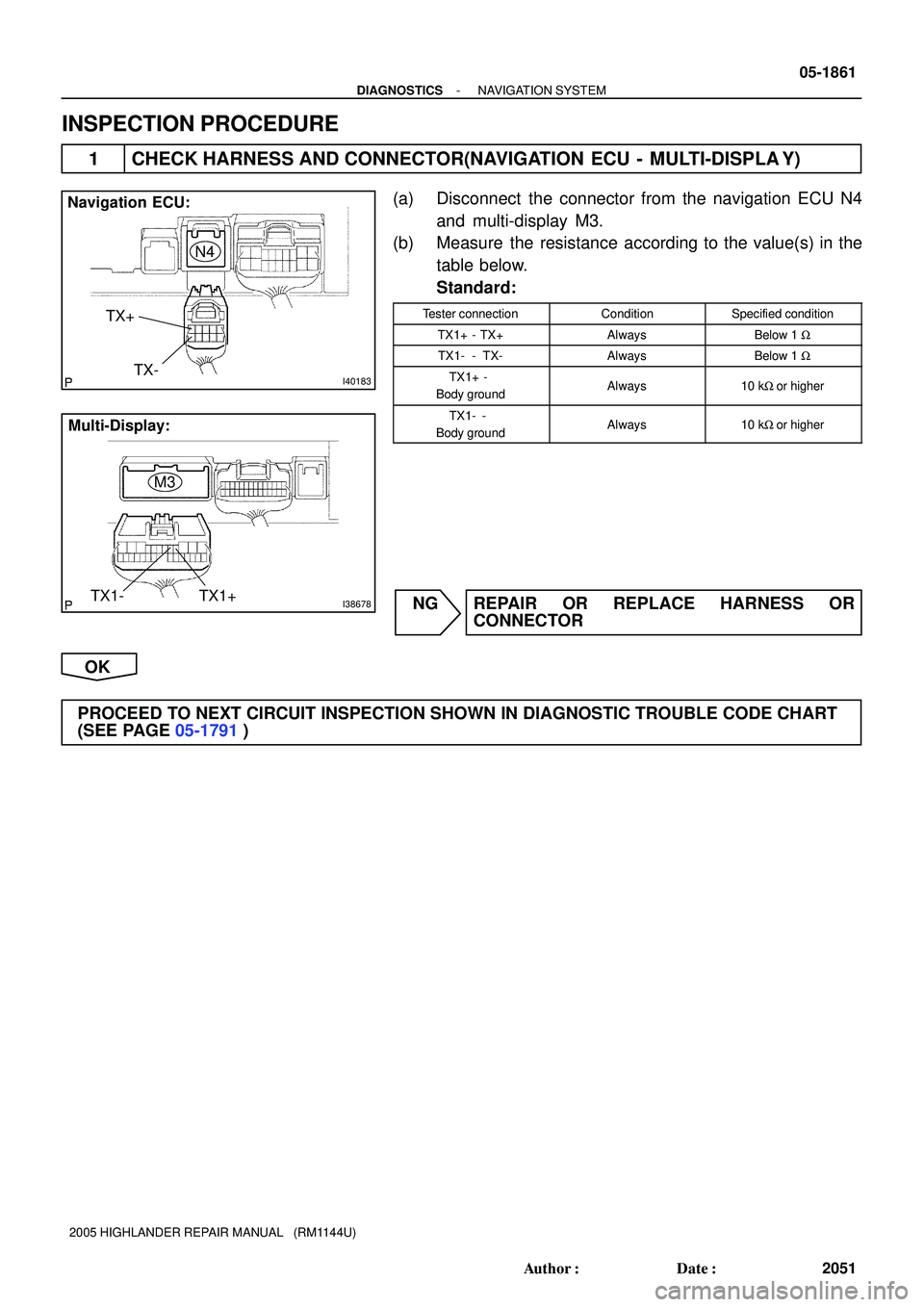
INSPECTION PROCEDURE
1 CHECK HARNESS AND CONNECTOR(NAVIGATION ECU - MULTI-DISPLA Y)
(a) Disconnect the connector from the navigation ECU N4
and multi-display M3.
(b) Measure the resistance according to the value(s) in the
table below.
Standard:
Tester connectionConditionSpecified condition
TX1+ - TX+AlwaysBelow 1 W
TX1- - TX-AlwaysBelow 1 W
TX1+ -
Body groundAlways10 kW or higher
TX1- -
Body groundAlways10 kW or higher
NG REPAIR OR REPLACE HARNESS OR
CONNECTOR
OK
PROCEED TO NEXT CIRCUIT INSPECTION SHOWN IN DIAGNOSTIC TROUBLE CODE CHART
(SEE PAGE 05-1791)
Page 1601 of 2572
I34966
Multi-Display
Gateway ECU
GTX+
GTX- TX3+
TX3-
M412 M411
L BR
G512 G55 05-1862
- DIAGNOSTICSNAVIGATION SYSTEM
2052 Author�: Date�:
2005 HIGHLANDER REPAIR MANUAL (RM1144U)
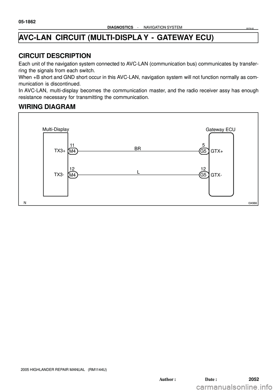
AVC-LAN CIRCUIT (MULTI-DISPLA Y - GATEWAY ECU)
CIRCUIT DESCRIPTION
Each unit of the navigation system connected to AVC-LAN (communication bus) communicates by transfer-
ring the signals from each switch.
When +B short and GND short occur in this AVC-LAN, navigation system will not function normally as com-
munication is discontinued.
In AVC-LAN, multi-display becomes the communication master, and the radio receiver assy has enough
resistance necessary for transmitting the communication.
WIRING DIAGRAM
05IT8-02
Page 1602 of 2572
I38998
Multi-Display:
TX3+
TX3-
M4
I40180
Gateway ECU:
GTX+
GTX-G5
- DIAGNOSTICSNAVIGATION SYSTEM
05-1863
2053 Author�: Date�:
2005 HIGHLANDER REPAIR MANUAL (RM1144U)
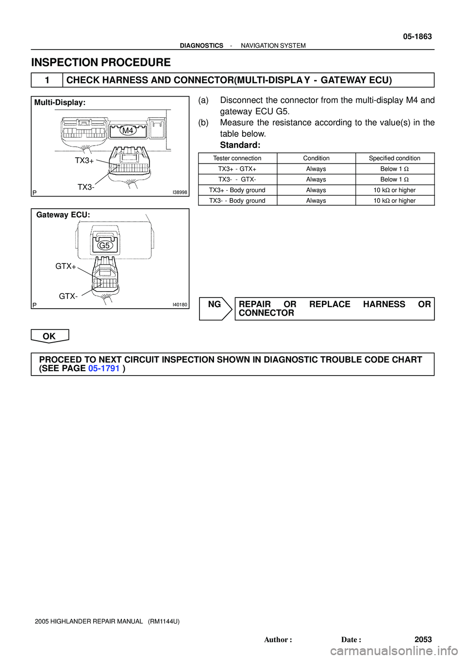
INSPECTION PROCEDURE
1 CHECK HARNESS AND CONNECTOR(MULTI-DISPLA Y - GATEWAY ECU)
(a) Disconnect the connector from the multi-display M4 and
gateway ECU G5.
(b) Measure the resistance according to the value(s) in the
table below.
Standard:
Tester connectionConditionSpecified condition
TX3+ - GTX+AlwaysBelow 1 W
TX3- - GTX-AlwaysBelow 1 W
TX3+ - Body groundAlways10 kW or higher
TX3- - Body groundAlways10 kW or higher
NG REPAIR OR REPLACE HARNESS OR
CONNECTOR
OK
PROCEED TO NEXT CIRCUIT INSPECTION SHOWN IN DIAGNOSTIC TROUBLE CODE CHART
(SEE PAGE 05-1791)
Page 1603 of 2572
05IS3-02
I38224
I38225
I38226
05-1764
- DIAGNOSTICSNAVIGATION SYSTEM
1954 Author�: Date�:
2005 HIGHLANDER REPAIR MANUAL (RM1144U)
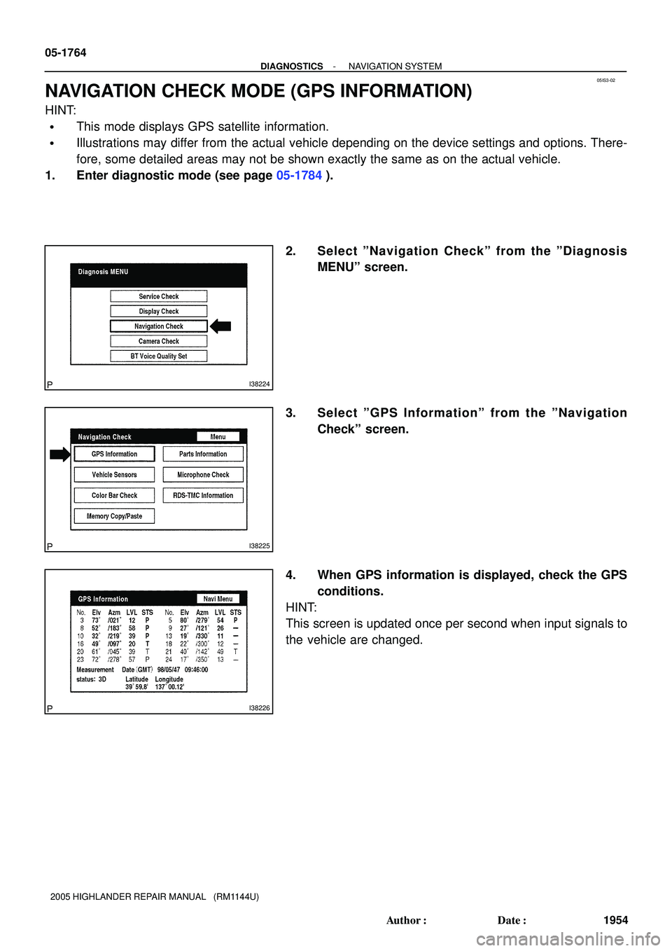
NAVIGATION CHECK MODE (GPS INFORMATION)
HINT:
�This mode displays GPS satellite information.
�Illustrations may differ from the actual vehicle depending on the device settings and options. There-
fore, some detailed areas may not be shown exactly the same as on the actual vehicle.
1. Enter diagnostic mode (see page 05-1784).
2. Select ºNavigation Checkº from the ºDiagnosis
MENUº screen.
3. Select ºGPS Informationº from the ºNavigation
Checkº screen.
4. When GPS information is displayed, check the GPS
conditions.
HINT:
This screen is updated once per second when input signals to
the vehicle are changed.
Page 1604 of 2572
05IS5-02
I38224
I38229
I38230
05-1766
- DIAGNOSTICSNAVIGATION SYSTEM
1956 Author�: Date�:
2005 HIGHLANDER REPAIR MANUAL (RM1144U)
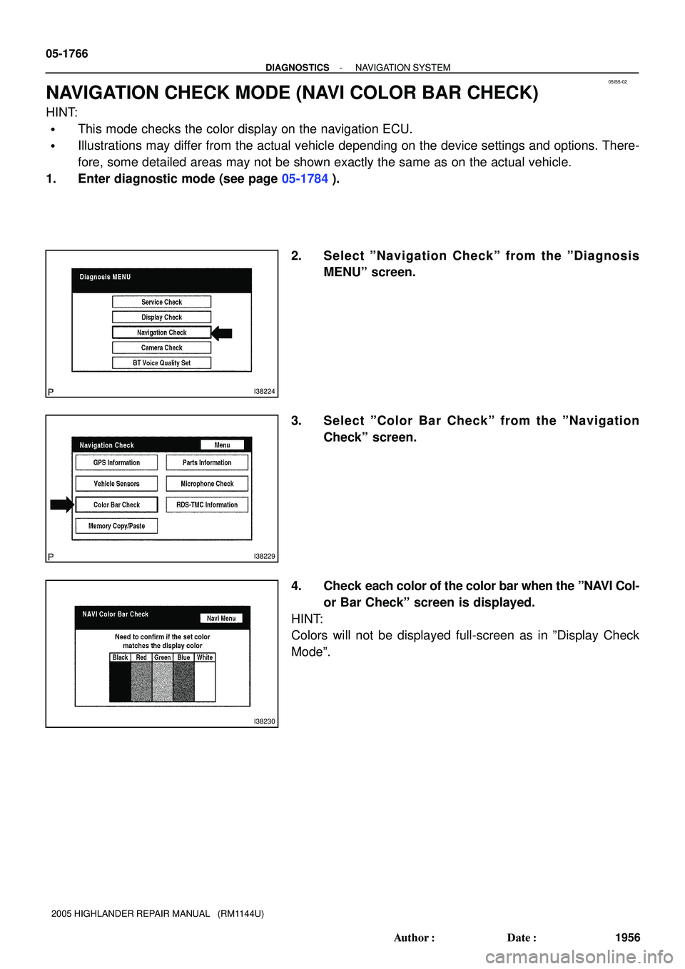
NAVIGATION CHECK MODE (NAVI COLOR BAR CHECK)
HINT:
�This mode checks the color display on the navigation ECU.
�Illustrations may differ from the actual vehicle depending on the device settings and options. There-
fore, some detailed areas may not be shown exactly the same as on the actual vehicle.
1. Enter diagnostic mode (see page 05-1784).
2. Select ºNavigation Checkº from the ºDiagnosis
MENUº screen.
3. Select ºColor Bar Checkº from the ºNavigation
Checkº screen.
4. Check each color of the color bar when the ºNAVI Col-
or Bar Checkº screen is displayed.
HINT:
Colors will not be displayed full-screen as in ºDisplay Check
Modeº.