Page 1384 of 2572

Position information/*4
DisplayContents
PositionLatitude and lo")
I38593
*1
*2
*3
I38594
*1
*2
*3
*4
- DIAGNOSTICSNAVIGATION SYSTEM
05-1773
1963 Author�: Date�:
2005 HIGHLANDER REPAIR MANUAL (RM1144U)
Position information/*4
DisplayContents
PositionLatitude and longitude information on the current position is displayed.
Date information/*5
DisplayContents
DateThe date/time information obtained from GPS signal is displayed in Greenwich
mean time (GMT). The last 4 digits are displayed.
(c) Vehicle Signal Check Screen
Vehicle signal
DisplayContents
REV/*1REV signal ON/OFF state is displayed.
SPD/*2SPD signal condition is displayed.
Sensor signal
DisplayContents
Gyro sensor/*3Gyro sensor output condition is displayed (when the vehicle runs straight or is sta-
tionary, the voltage is approximately 2.5 V).
HINT:
Signals are updated once per second only when vehicle sensor signals are changed.
(d) Parts Information Screen
Screen description
DisplayContents
Navigation Manufacturer/*1Navigation ECU manufacturer is displayed.
Navigation Version No./*2Navigation ECU version is displayed.
Disc Manufacturer/*3Map disc manufacturer is displayed.
Disc Version No./*4Map disc version is displayed.
Page 1385 of 2572
I38595
05-1774
- DIAGNOSTICSNAVIGATION SYSTEM
1964 Author�: Date�:
2005 HIGHLANDER REPAIR MANUAL (RM1144U)
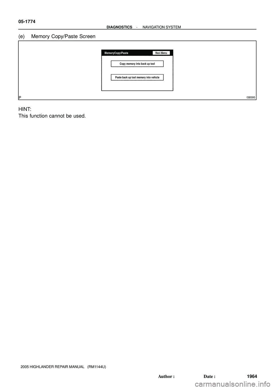
(e) Memory Copy/Paste Screen
HINT:
This function cannot be used.
Page 1386 of 2572

DIAGNOSTIC START-UP/FINISH
HINT:
�Illustrations may differ from the")
05ISA-02
I40190
I38204
I38205
05-1784
- DIAGNOSTICSNAVIGATION SYSTEM
1974 Author�: Date�:
2005 HIGHLANDER REPAIR MANUAL (RM1144U)
DIAGNOSTIC START-UP/FINISH
HINT:
�Illustrations may differ from the actual vehicle depending on the device settings and options. There-
fore, some detailed areas may not be shown exactly the same as on the actual vehicle.
�After the ignition switch is turned on, check that the map is displayed before starting the diagnostic
mode. Otherwise, some items cannot be checked.
1. There are 2 methods to start diagnostic mode. Start the mode by using one of them.
2. Method 1
(a) Start the engine.
(b) While pressing and holding ºINFOº switch, operate light
control switch, OFF " TAIL " OFF " TAIL " OFF "
TAIL " OFF.
(c) The diagnostic mode starts and the service check screen
(ºSystem Check Modeº) will be displayed. Service inspec-
tion starts automatically and the result will be displayed.
3. Method 2
(a) Start the engine.
(b) Switch to the ºDisplay Checkº screen.
(c) From the display adjustment screen, touch the corners of
the screen in the following order: upper left " lower left
"upper left " lower left " upper left " lower left.
(d) The diagnostic mode starts and ºService Checkº screen
will be displayed. Service inspection starts automatically
and the result will be displayed.
4. Diagnosis MENU
(a) Diagnostic screen will be displayed by pressing the menu
switch on the service check screen.
Page 1387 of 2572
- DIAGNOSTICSNAVIGATION SYSTEM
05-1785
1975 Author�: Date�:
2005 HIGHLANDER REPAIR MANUAL (RM1144U)
5. There are 2 methods to exit. Use one of them.
(a) Turn the ignition switch off.
(b) Press the ºDisplayº switch for 3 seconds.
Page 1567 of 2572
I39199
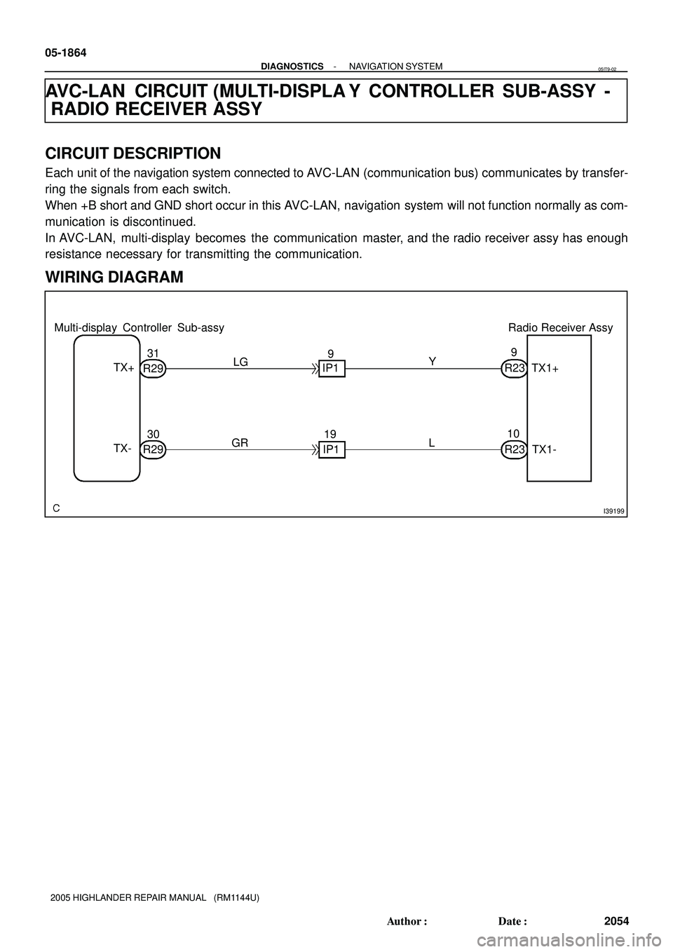
Multi-display Controller Sub-assy Radio Receiver Assy
TX1+
TX1- TX+
TX-
R2930 R2931
GRLG
IP119 IP19
L Y
R2310 R239 05-1864
- DIAGNOSTICSNAVIGATION SYSTEM
2054 Author�: Date�:
2005 HIGHLANDER REPAIR MANUAL (RM1144U)
AVC-LAN CIRCUIT (MULTI-DISPLA Y CONTROLLER SUB-ASSY -
RADIO RECEIVER ASSY
CIRCUIT DESCRIPTION
Each unit of the navigation system connected to AVC-LAN (communication bus) communicates by transfer-
ring the signals from each switch.
When +B short and GND short occur in this AVC-LAN, navigation system will not function normally as com-
munication is discontinued.
In AVC-LAN, multi-display becomes the communication master, and the radio receiver assy has enough
resistance necessary for transmitting the communication.
WIRING DIAGRAM
05IT9-02
Page 1568 of 2572

I40222
TX1+ TX1-
R23
I34639
Multi-display Controller Sub-assy:
R29
TX+TX-
I40203
Radio Receive Assy:
R23
TX1+
TX1-
- DIAGNOSTICSNAVIGATION SYSTEM
05-1865
2055 Author�: Date�:
2005 HIGHLANDER REPAIR MANUAL (RM1144U)
INSPECTION PROCEDURE
1 INSPECT RADIO RECEIVER ASSY
(a) Measure the resistance according to the value(s) in the
table below.
Standard:
Tester connectionConditionSpecified condition
TX1+ - TX1-Always60 to 80 W
NG REPLACE RADIO RECEIVER ASSY
(SEE PAGE 67-6)
OK
2 CHECK HARNESS AND CONNECTOR(MULTI-DISPLA Y CONTROLLER
SUB-ASSY - RADIO RECEIVER ASSY)
(a) Disconnect the connectors from the multi-display control-
ler sub-assy R29 and radio receiver assy R23.
(b) Measure the resistance according to the value(s) in the
table below.
Standard:
Tester connectionConditionSpecified condition
TX+ - TX1+AlwaysBelow 1 W
TX- - TX1-AlwaysBelow 1 W
TX+ - Body groundAlways10 kW or higher
TX- - Body groundAlways10 kW or higher
NG REPAIR OR REPLACE HARNESS OR
CONNECTOR
OK
PROCEED TO NEXT CIRCUIT INSPECTION SHOWN IN DIAGNOSTIC TROUBLE CODE CHART
(SEE PAGE 05-1791)
Page 1569 of 2572
I39187
Gateway ECU
Center J/B
Instrument Panel J/B
Passenger Side J/B
Instrument Panel J/B I15
IGNITION SW
F7
FL Block
Engine Room J/B
Center J/BIG
ACC
BATT
GNDCG RAD No.2IG1
ACC
IG1 AM1AM1
ALT
D.C.C
DOME
IB Battery FL MAINW-B W-B
W-B W
3F 13
3G6 3G5
G5 14G57 2A3
2I1
3 12 W43
2W
1C6
2
11A1V
IK312
V
4H6
4D11
V
IL211
LG L G
1C2 1C7
1J6 1K 10
W GR
3F9 3A8 3A 10
3F8 3D1 3I1
LG SBB
G58 G59 G52
B 05-1834
- DIAGNOSTICSNAVIGATION SYSTEM
2024 Author�: Date�:
2005 HIGHLANDER REPAIR MANUAL (RM1144U)
POWER SOURCE CIRCUIT (GATEWAY ECU)
CIRCUIT DESCRIPTION
This circuit provides power to the gateway ECU.
WIRING DIAGRAM
05ISY-02
Page 1570 of 2572
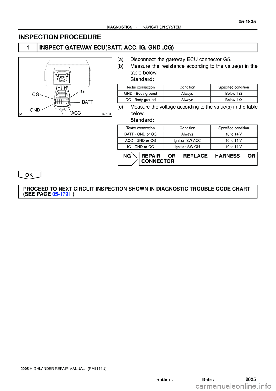
I40180
G5
CG
GNDIG
BATT
ACC
- DIAGNOSTICSNAVIGATION SYSTEM
05-1835
2025 Author�: Date�:
2005 HIGHLANDER REPAIR MANUAL (RM1144U)
INSPECTION PROCEDURE
1 INSPECT GATEWAY ECU(BATT, ACC, IG, GND ,CG)
(a) Disconnect the gateway ECU connector G5.
(b) Measure the resistance according to the value(s) in the
table below.
Standard:
Tester connectionConditionSpecified condition
GND - Body groundAlwaysBelow 1 W
CG - Body groundAlwaysBelow 1 W
(c) Measure the voltage according to the value(s) in the table
below.
Standard:
Tester connectionConditionSpecified condition
BATT - GND or CGAlways10 to 14 V
ACC - GND or CGIgnition SW ACC10 to 14 V
IG - GND or CGIgnition SW ON10 to 14 V
NG REPAIR OR REPLACE HARNESS OR
CONNECTOR
OK
PROCEED TO NEXT CIRCUIT INSPECTION SHOWN IN DIAGNOSTIC TROUBLE CODE CHART
(SEE PAGE 05-1791)