Page 1589 of 2572

4 CHECK HARNE")
I40178I38999I40553
Navigation ECU:
Wire Harness Side:
Front No.2 Speaker AssyN3
AUO+
AUO-
05-1666
- DIAGNOSTICSAUDIO SYSTEM
1856 Author�: Date�:
2005 HIGHLANDER REPAIR MANUAL (RM1144U)
4 CHECK HARNESS AND CONNECTOR(NAVIGATION ECU - FRONT NO. 2
SPEAKER ASSY)
(a) Disconnect the connectors from the navigation ECU and
speaker.
(b) Measure the resistance according to the values in the
table below.
Standard:
Tester connectionConditionSpecified condition
AUO+ - 1AlwaysBelow 1 W
AUO- - 2AlwaysBelow 1 W
AUO+ - Body groundAlways10 kW or higher
AUO- - Body groundAlways10 kW or higher
NG REPAIR OR REPLACE HARNESS OR
CONNECTOR
OK
5 INSPECT FRONT NO. 2 SPEAKER ASSY
(a) Check that malfunction disappears when another speaker in a good condition is installed.
OK: Malfunction disappears.
HINT:
�Connect all the connectors to the speakers.
�When there is a possibility that either right or left front speaker is defective, inspect by interchanging
the right one and the left one.
OK REPLACE FRONT NO. 2 SPEAKER ASSY
(SEE PAGE 67-1 1)
NG
Page 1590 of 2572

I38999I38233I40554
Wire Harness Side:
Front No.1 Speaker Assy Wire Harness Side:
Front No.2 Speaker Assy
- DIAGNOSTICSAUDIO SYSTEM
05-1667
1857 Author�: Date�:
2005 HIGHLANDER REPAIR MANUAL (RM1144U)
6 CHECK HARNESS AND CONNECTOR(FRONT NO. 2 SPEAKER ASSY - FRONT
NO. 1 SPEAKER ASSY)
(a) Disconnect the connectors from the front No.2 speaker
assy and front No.1 speaker assy.
(b) Measure the resistance according to the values in the
table below.
Tester connectionConditionSpecified condition
3 (Front No.2 speaker
Assy) - 1 (Front No.1
speaker Assy)
AlwaysBelow 1 W
4 (Front No.2 speaker
Assy) - 2 (Front No.1
speaker Assy)
AlwaysBelow 1 W
3 (Front No.2 speaker
Assy) - Body groundAlways10 kW or higher
4 (Front No.2 speaker
Assy) - Body groundAlways10 kW or higher
NG REPAIR OR REPLACE HARNESS OR
CONNECTOR
OK
7 INSPECT FRONT NO. 1 SPEAKER ASSY
(a) Resistance check
(1) Measure the resistance between the terminals of the speaker.
NOTICE:
The speaker should not be removed for checking.
Standard: 4 W
NG REPLACE FRONT NO. 1 SPEAKER ASSY
(SEE PAGE 67-10)
OK
REPLACE NAVIGATION ECU (SEE PAGE 67-9)
Page 1591 of 2572

I40178I39179I40555
Navigation ECU:
Stereo Component Amplifier Assy:N3
AUI+
AUI-
S23
FL+
FL-
I40178
N3
AUI+
AUI-AUO+
AUO-
05-1668
- DIAGNOSTICSAUDIO SYSTEM
1858 Author�: Date�:
2005 HIGHLANDER REPAIR MANUAL (RM1144U)
8 CHECK HARNESS AND CONNECTOR(NAVIGATION ECU - STEREO COMPONENT
AMPLIFIER ASSY)
(a) Disconnect the connectors from the navigation ECU and
stereo component amplifier assy.
(b) Measure the resistance according to the values in the
table below.
Standard:
Tester connectionConditionSpecified condition
AUI+ - FL+AlwaysBelow 1 W
AUI- - FL-AlwaysBelow 1 W
AUI+ - Body groundAlways10 kW or higher
AUI- - Body groundAlways10 kW or higher
NG REPAIR OR REPLACE HARNESS OR
CONNECTOR
OK
9 INSPECT NAVIGATION ECU
(a) Disconnect the connector from the navigation ECU.
(b) Measure the resistance according to the values in the
table below.
Standard:
Tester connectionConditionSpecified condition
AUI+ - AUO+AlwaysBelow 1 W
AUI- - AUO-AlwaysBelow 1 W
NG REPLACE NAVIGATION ECU
(SEE PAGE 67-9)
OK
PROCEED TO NEXT CIRCUIT INSPECTION SHOWN IN PROBLEM SYMPTOMS TABLE
(SEE PAGE 05-1632)
Page 1592 of 2572
I39188
Multi-Display
Center J/B Instrument Panel J/B
Engine Room R/B
Instrument Panel J/B I15
IGNITION SW
F7
FL Block
Center J/BIG
ACC
+B1
GND1
Battery FL MAINALTRAD No.2ECU-IG
W-B W-B
IB W
WB IG1 AM1 ACC
WAM1 CRT
VVJ17
J/C
VVBRO
V R
M3 10
M311
M3 12 3E3 3G7
3A 13 3A1
1K3 1K9
1C2 1C7
L G
IK2 16
A
AIL16
2
1 2 2
42 3
1C6
211A1
1
3 2
3F13
3I6
M33 05-1828
- DIAGNOSTICSNAVIGATION SYSTEM
2018 Author�: Date�:
2005 HIGHLANDER REPAIR MANUAL (RM1144U)
POWER SOURCE CIRCUIT (MULTI-DISPLA Y)
CIRCUIT DESCRIPTION
This circuit provides power to the multi-display.
WIRING DIAGRAM
05CEF-10
Page 1593 of 2572
I38678
M3
GND1 IG
ACC
+B1
- DIAGNOSTICSNAVIGATION SYSTEM
05-1829
2019 Author�: Date�:
2005 HIGHLANDER REPAIR MANUAL (RM1144U)
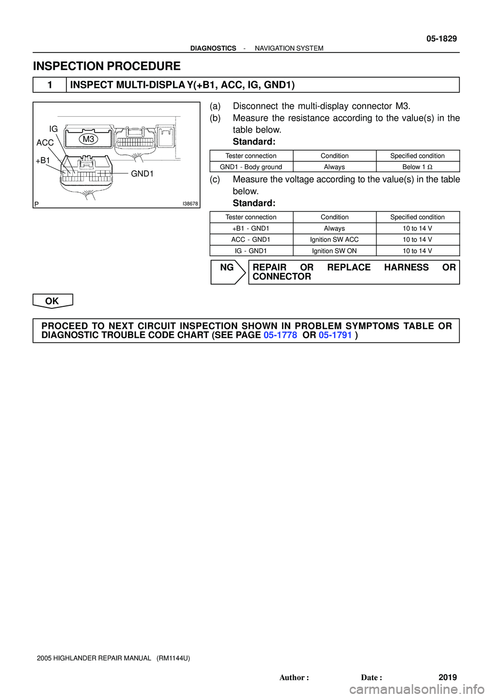
INSPECTION PROCEDURE
1 INSPECT MULTI-DISPLA Y(+B1, ACC, IG, GND1)
(a) Disconnect the multi-display connector M3.
(b) Measure the resistance according to the value(s) in the
table below.
Standard:
Tester connectionConditionSpecified condition
GND1 - Body groundAlwaysBelow 1 W
(c) Measure the voltage according to the value(s) in the table
below.
Standard:
Tester connectionConditionSpecified condition
+B1 - GND1Always10 to 14 V
ACC - GND1Ignition SW ACC10 to 14 V
IG - GND1Ignition SW ON10 to 14 V
NG REPAIR OR REPLACE HARNESS OR
CONNECTOR
OK
PROCEED TO NEXT CIRCUIT INSPECTION SHOWN IN PROBLEM SYMPTOMS TABLE OR
DIAGNOSTIC TROUBLE CODE CHART (SEE PAGE 05-1778 OR 05-1791)
Page 1594 of 2572
I39195
Combination Meter Assy
Center J/BMulti-Display
SPD M325
W
3F6
3J9
W
C1213
- DIAGNOSTICSNAVIGATION SYSTEM
05-1841
2031 Author�: Date�:
2005 HIGHLANDER REPAIR MANUAL (RM1144U)
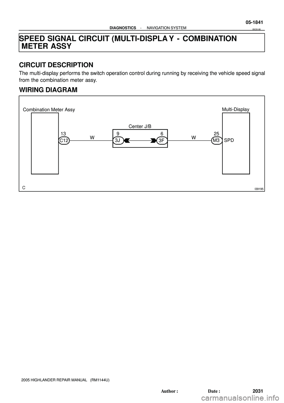
SPEED SIGNAL CIRCUIT (MULTI-DISPLA Y - COMBINATION
METER ASSY
CIRCUIT DESCRIPTION
The multi-display performs the switch operation control during running by receiving the vehicle speed signal
from the combination meter assy.
WIRING DIAGRAM
05CEI-08
Page 1595 of 2572
I38678
M3
Multi-Display:
SPD
I40181
Combination Meter Assy:
C12
13
05-1842
- DIAGNOSTICSNAVIGATION SYSTEM
2032 Author�: Date�:
2005 HIGHLANDER REPAIR MANUAL (RM1144U)
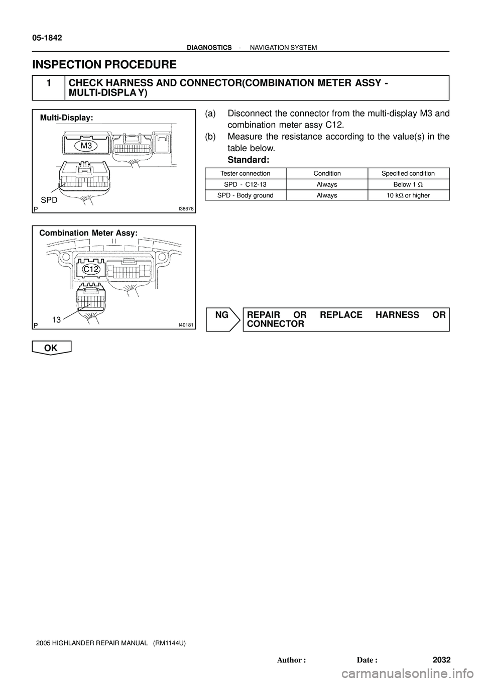
INSPECTION PROCEDURE
1 CHECK HARNESS AND CONNECTOR(COMBINATION METER ASSY -
MULTI-DISPLA Y)
(a) Disconnect the connector from the multi-display M3 and
combination meter assy C12.
(b) Measure the resistance according to the value(s) in the
table below.
Standard:
Tester connectionConditionSpecified condition
SPD - C12-13AlwaysBelow 1 W
SPD - Body groundAlways10 kW or higher
NG REPAIR OR REPLACE HARNESS OR
CONNECTOR
OK
Page 1596 of 2572
I40187
C12
13
IG Voltage
9 to 14 V
0
Turn the wheel Below 2 V
- DIAGNOSTICSNAVIGATION SYSTEM
05-1843
2033 Author�: Date�:
2005 HIGHLANDER REPAIR MANUAL (RM1144U)
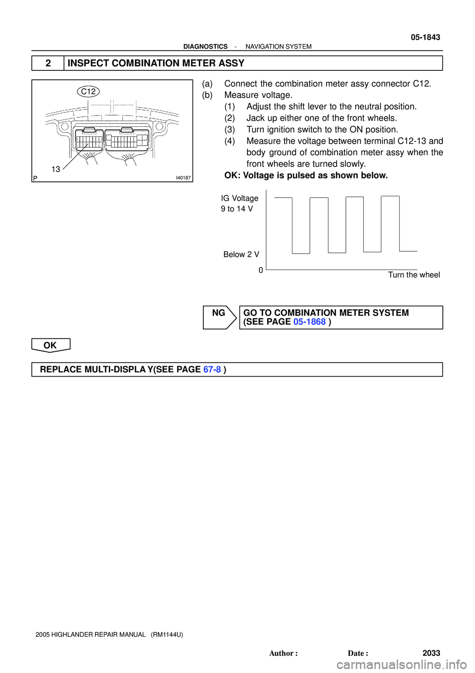
2 INSPECT COMBINATION METER ASSY
(a) Connect the combination meter assy connector C12.
(b) Measure voltage.
(1) Adjust the shift lever to the neutral position.
(2) Jack up either one of the front wheels.
(3) Turn ignition switch to the ON position.
(4) Measure the voltage between terminal C12-13 and
body ground of combination meter assy when the
front wheels are turned slowly.
OK: Voltage is pulsed as shown below.
NG GO TO COMBINATION METER SYSTEM
(SEE PAGE 05-1868)
OK
REPLACE MULTI-DISPLA Y(SEE PAGE 67-8)