Page 700 of 1897
DI-318
- DIAGNOSTICSABS WITH EBD & BA & TRAC & VSC SYSTEM
474 Author�: Date�:
2001 AVALON (RM808U)
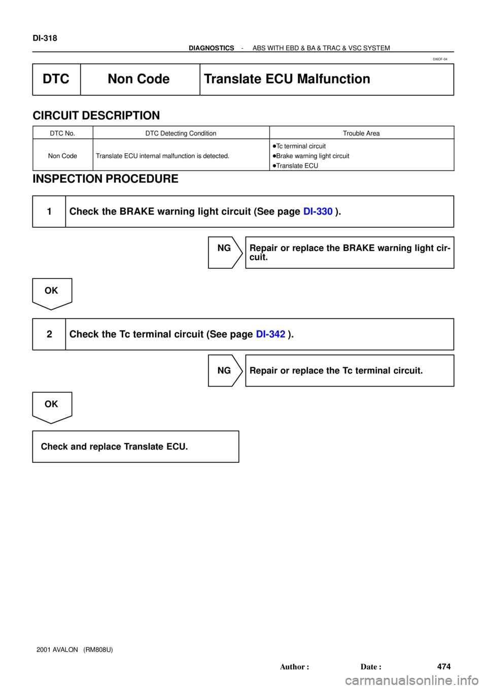
DTC Non Code Translate ECU Malfunction
CIRCUIT DESCRIPTION
DTC No.DTC Detecting ConditionTrouble Area
Non CodeTranslate ECU internal malfunction is detected.
�Tc terminal circuit
�Brake warning light circuit
�Translate ECU
INSPECTION PROCEDURE
1 Check the BRAKE warning light circuit (See page DI-330).
NG Repair or replace the BRAKE warning light cir-
cuit.
OK
2 Check the Tc terminal circuit (See page DI-342).
NG Repair or replace the Tc terminal circuit.
OK
Check and replace Translate ECU.
DI6OF-04
Page 701 of 1897

DTC Normal Code Malfunction in ECM
CIRCUIT DESCRIPTION
If any trouble occurs in the ECM control sys")
- DIAGNOSTICSABS WITH EBD & BA & TRAC & VSC SYSTEM
DI-317
473 Author�: Date�:
2001 AVALON (RM808U)
DTC Normal Code Malfunction in ECM
CIRCUIT DESCRIPTION
If any trouble occurs in the ECM control system, the ECU prohibits ABS & VSC control.
DTC No.DTC Detecting ConditionTrouble Area
Normal Code
Conditions 1., 2,. 3, or 4,continue for 5 sec. or more:
1. Engine malfunction signal is sent from ECM.
2. Shift malfunction signal is sent from ECM
3. The shift position is other than P and N range input volt-
age is 8 V or more.
4. The shift position is PN or rev and D range input voltage
is 8 V or more.�ECM circuit
�ECM
�Brake fluid level
�Brake fluid level warning switch circuit
�Steering angle sensor
�ABS & BA & TRAC & VSC ECU
INSPECTION PROCEDURE
1 Is DTC out put for ECM?
Check DTC on page DI-3.
YES Repair engine control system according to the
output code.
NO
2 Check the DTC for the ABS and VSC (See page DI-252).
*1 Repair ABS and VSC control system according
to the code output.
*2
Check and replace translate ECU.
*1: Output NG code except for DTC of VSC system C1301/42
*2: Output NG code DTC of VSC system C1301/42 only
DI6OF-03
Page 705 of 1897
F09806
ABS & BA &
TRAC & VSC ECU
A20 E1
EB
T5TC 84
LG-R
4A
4B 4H
4A6
19
196 LG-R
LG-R
LG-R 21
TC Translate ECU
W-B311LG-R D1
DLC1
TC22
II2 3A 3G4 13
LG-R D2
DLC2
E1 TC
4J/B No. 3 J/B No. 4
F10163
DLC2
Tc E
1DLC1
TcON
DI-342
- DIAGNOSTICSABS WITH EBD & BA & TRAC & VSC SYSTEM
498 Author�: Date�:
2001 AVALON (RM808U)
Tc Terminal Circuit
CIRCUIT DESCRIPTION
Connecting between terminals Tc and E1 of the DLC1 or the DLC2 causes the ECU to display DTC by blink-
ing the ABS warning light, VSC warning light and BRAKE warning light.
WIRING DIAGRAM
INSPECTION PROCEDURE
1 Check voltage between terminals Tc and E1.
CHECK:
(a) Turn the ignition switch ON.
(b) Measure the voltage between terminals Tc and E
1 of or
DLC1 or terminal Tc of DLC2 and body ground.
OK:
Voltage: 10 - 14 V
OK If each warning light does not blink even after Tc
and E
1 are connected, the ECU may be defec-
tive.
NG
DI6OO-01
Page 707 of 1897
F09808
ABS & BA &
TRAC & VSC ECU
A20TS 42
LG-B
4A
4B4A J/B No. 4
3
12
12 LG-B
LG-B LG-B
II2 11
16 3TS
D1
DLC1
EBW-B
T524
TS Translate ECU D3
DLC3
E1 TSLG-B LG-B
14
AB0119S08096
F00446
Ts
DLC1Ts
DLC1Ts
DLC1Ts
DLC1Ts
DLC1 ONTs
DLC1 E
1
DI-344
- DIAGNOSTICSABS WITH EBD & BA & TRAC & VSC SYSTEM
500 Author�: Date�:
2001 AVALON (RM808U)
Ts Terminal Circuit
CIRCUIT DESCRIPTION
The sensor check circuit detects abnormality in the speed sensor signal which cannot be detected with the
DTC check.
Connecting terminals Ts and E
1 of the DLC1 starts the check.
WIRING DIAGRAM
INSPECTION PROCEDURE
1 Check voltage between terminals Ts and E1 of DLC1.
CHECK:
(a) Turn the ignition switch ON.
(b) Measure the voltage between terminals Ts and E
1 of
DLC1.
OK:
Voltage: 10 - 14 V
OK If ABS warning light does not blink even after Ts
and E
1 are connected, the ECU may be defec-
tive.
NG
DI6OP-03
Page 709 of 1897

F09811
Battery
FL MAIN
B F61 F10 F81
1
ALT
FL
BlockB-L
2G
2H1 1 5
5 1 2AM1 Engine Room R/B No. 5
Engine Room J/BB W-LW-L
IF17 W-R
2
IG1 AM1 4Ignition Switch WDriver Side J/B
1G1
1B 13
1B3
1C4
3
4 12 IG1 RelayECU-IG
No. 2
W-B
IG Y-R
L-WABS & BA &
TRAC & VSC ECU
A20 V9
VSC Warning
Buzzer
BZ 86
Buzzer1 2
- DIAGNOSTICSABS WITH EBD & BA & TRAC & VSC SYSTEM
DI-339
495 Author�: Date�:
2001 AVALON (RM808U)
VSC Buzzer Circuit
CIRCUIT DESCRIPTION
The VSC buzzer sounds during VSC operation.
WIRING DIAGRAM
INSPECTION PROCEDURE
HINT:
Start the inspection from step 1 in case of using the TOYOTA hand-held tester and start from step 3 in case
of not using the TOYOTA hand-held tester.
1 Check operation of the VSC buzzer.
PREPARATION:
(a) Connect the TOYOTA hand-held tester to the DLC3.
(b) Turn the ignition switch ON and push the TOYOTA hand-held tester main switch ON.
(c) Select the ACTIVE TEST mode on the TOYOTA hand-held tester.
CHECK:
Check ºON-OFFº function of the VSC buzzer with the TOYOTA hand-held tester.
OK Check and replace ABS & BA & TRAC & VSC
ECU.
NG
DI6ON-03
Page 715 of 1897
F09818
ABS & BA &
TRAC & VSC ECU
VSCW A2070
P-B
R-B 15
4D
4F 134 4F15
4C P-BJ/B No. 4
M6 M6
R-B4
10 Multi Display
Driver Side J/B
1G1
1D 10
1B3
1C4
3
4 12 IG1 RelayGAUGE
No. 1
W-R 2
IG1 AM1
4 Ignition Switch
W-L W
IF1
7
W-L
5
5 1 2AM1 Engine Room R/B No. 5
B2G 2H11W-B
IG B-L
Battery
FL MAIN
B
F61 F10 F81 1
ALT
FL BlockVSC
Engine Room J/B
- DIAGNOSTICSABS WITH EBD & BA & TRAC & VSC SYSTEM
DI-327
483 Author�: Date�:
2001 AVALON (RM808U)
VSC Warning Light Circuit
CIRCUIT DESCRIPTION
If the ECU stores DTC to be necessary to shut down VSC operation, the VSC warning light lights on the
combination meter.
WIRING DIAGRAM
DI6OJ-03
Page 716 of 1897
DI-328
- DIAGNOSTICSABS WITH EBD & BA & TRAC & VSC SYSTEM
484 Author�: Date�:
2001 AVALON (RM808U)
INSPECTION PROCEDURE
HINT:
Start the inspection from step 1 in case of using the TOYOTA hand-held tester and start from step 2 in case
of not using the TOYOTA hand-held tester.
1 Check operation of the VSC warning light.
PREPARATION:
(a) Connect the TOYOTA hand-held tester to the DLC3.
(b) Turn the ignition switch ON and push the TOYOTA hand-held tester main switch ON.
(c) Select the ACTIVE TEST mode on the TOYOTA hand-held tester.
CHECK:
Check that ºONº and ºOFFº of the VSC warning light can be shown on the combination meter with the TOYO-
TA hand-held tester.
OK Check and replace ABS & BA & TRAC & VSC
ECU.
NG
2 Is DTC output?
YES Repair circuit indicated by the output code.
NO
3 Check for open and short circuit in harness and connector between ABS & BA &
TRAC & VSC ECU and VSC warning light (See page IN-30).
NG Repair or replace harness or connector.
OK
Page 717 of 1897
- DIAGNOSTICSABS WITH EBD & BA & TRAC & VSC SYSTEM
DI-329
485 Author�: Date�:
2001 AVALON (RM808U)
4 Check VSC warning light.
See the combination meter troubleshooting on page BE-2.
NG Repair or replace combination meter.
OK
Check and replace ABS & BA & TRAC & VSC
ECU.