Page 1780 of 1897
Z15499
Oil
Reservoir
PS Vane
Pump PS Gear
SST Open
Z15500
Oil
Reservoir
PS Vane
Pump PS Gear
SST Open Lock Position
- STEERINGPOWER STEERING FLUID
SR-7
1470 Author�: Date�:
2001 AVALON (RM808U)
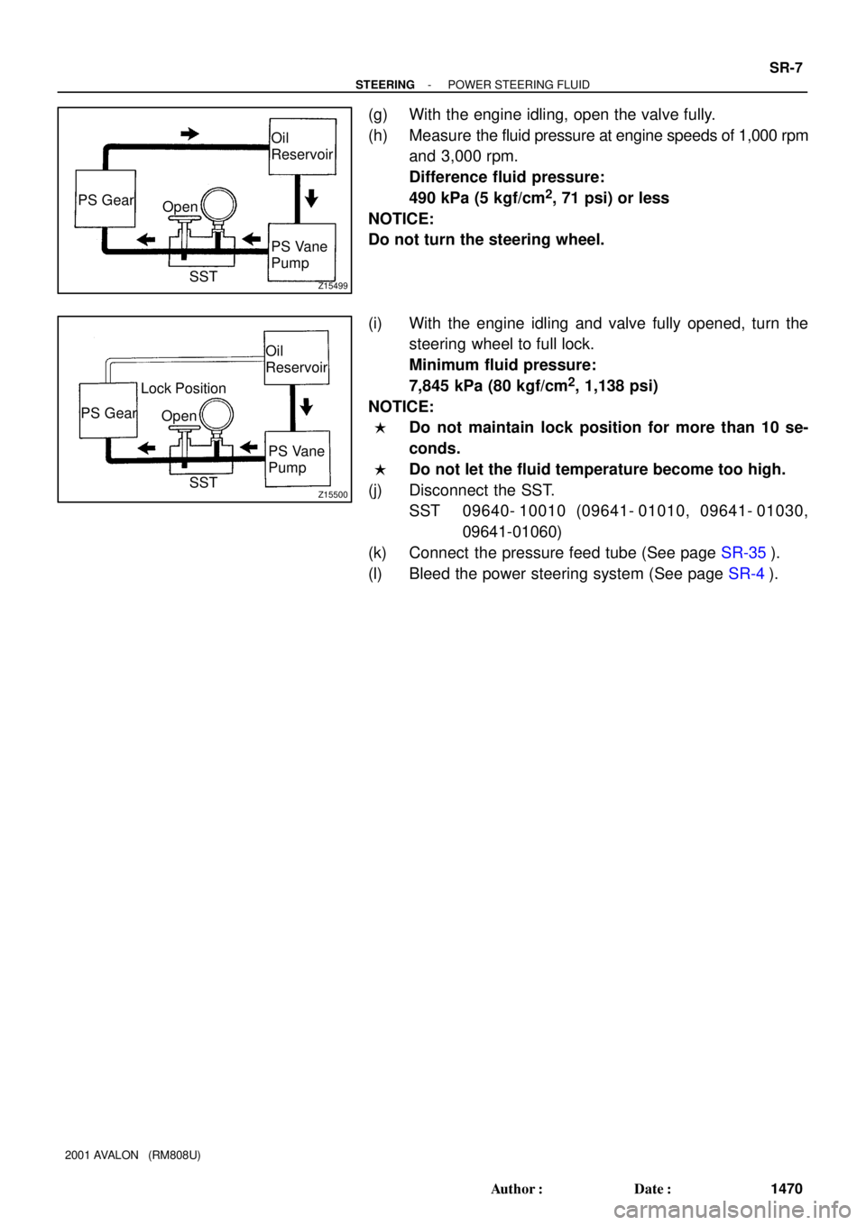
(g) With the engine idling, open the valve fully.
(h) Measure the fluid pressure at engine speeds of 1,000 rpm
and 3,000 rpm.
Difference fluid pressure:
490 kPa (5 kgf/cm
2, 71 psi) or less
NOTICE:
Do not turn the steering wheel.
(i) With the engine idling and valve fully opened, turn the
steering wheel to full lock.
Minimum fluid pressure:
7,845 kPa (80 kgf/cm
2, 1,138 psi)
NOTICE:
�Do not maintain lock position for more than 10 se-
conds.
�Do not let the fluid temperature become too high.
(j) Disconnect the SST.
SST 09640- 10010 (09641- 01010, 09641- 01030,
09641-01060)
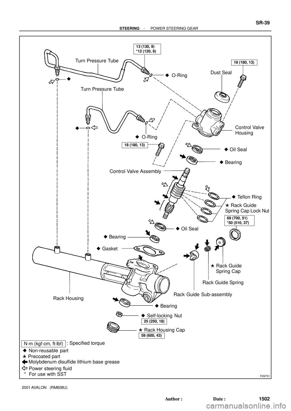
(k) Connect the pressure feed tube (See page SR-35).
(l) Bleed the power steering system (See page SR-4).
Page 1783 of 1897
F09751
� Non-reusable part� Oil Seal � O-Ring
Molybdenum disulfide lithium base grease
Power steering fluid � Precoated part� O-Ring Turn Pressure Tube
Dust Seal
�
Control Valve AssemblyControl Valve
Housing Turn Pressure Tube
�
� Oil Seal
� Bearing
� Teflon Ring
� Bearing
� Gasket
Rack Guide Spring
Rack Guide Sub-assembly
Rack Housing
� Bearing� Rack Guide
Spring Cap Lock Nut
� Rack Guide
Spring Cap
� Self-locking Nut
� Rack Housing Cap
13 (130, 9)
*12 (120, 9)
18 (180, 13)
18 (180, 13)
69 (700, 51)
*50 (510, 37)
25 (250, 18)
59 (600, 43)
N´m (kgf´cm, ft´lbf): Specified torque
* For use with SST
- STEERINGPOWER STEERING GEAR
SR-39
1502 Author�: Date�:
2001 AVALON (RM808U)
Page 1802 of 1897
SR0EN-06
F08851
Connector
Oil Pressure Switch
Union Bolt
� Gasket
Return HoseDrive Belt
Clamp Plate
Pressure Feed Tube
Pressure Feed Tube
PS Vane Pump AssemblyHolder
Clamp Plate
Clamp Plate
Front Fender Apron Seal RH
� Non-reusable part
43 (440, 32)
*29 (300, 22)
7.8 (80, 69 in.´lbf)
21 (210, 15)
52 (530, 38)
43 (440, 32)
25 (250, 18)
*22 (230, 17)
N´m (kgf´cm, ft´lbf): Specified torque
* For use with SST
- STEERINGPOWER STEERING VANE PUMP
SR-25
1488 Author�: Date�:
2001 AVALON (RM808U)
POWER STEERING VANE PUMP
COMPONENTS
Page 1803 of 1897
F08852
Pressure Port Union
� O-Ring
Flow Control Valve
Suction Port Union
SpringRear Housing
Rear
Bracket
Front Housing
Front Bracket
Vane Pump Shaft
Vane Pump PulleyVane Pump
Rotor
� Straight Pin
Wave Washer � O-Ring� O-Ring
� Gasket
Side Plate
Cam Ring
Vane Platex 10
� Oil Seal�
� Snap Ring
� Non-reusable part
Power steering fluid
83 (850, 62)
13 (130, 9)
43 (440, 32)
43 (440, 32)
17 (170, 12)
17 (170, 12)
44 (450, 33)
N´m (kgf´cm, ft´lbf): Specified torque
SR-26
- STEERINGPOWER STEERING VANE PUMP
1489 Author�: Date�:
2001 AVALON (RM808U)
Page 1808 of 1897
SR0ES-07
F08856
Pressure
Feed
Tube
Stopper
F08855
A
B
Z19285
Clamp
Engine Wire
SST Fulcrum
Length
- STEERINGPOWER STEERING VANE PUMP
SR-35
1498 Author�: Date�:
2001 AVALON (RM808U)
INSTALLATION
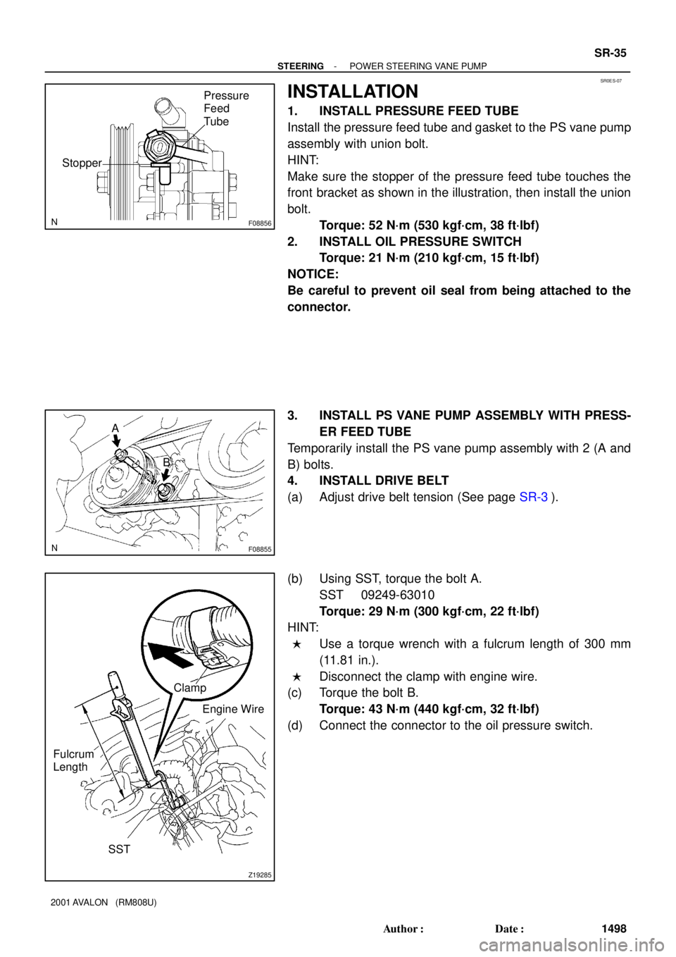
1. INSTALL PRESSURE FEED TUBE
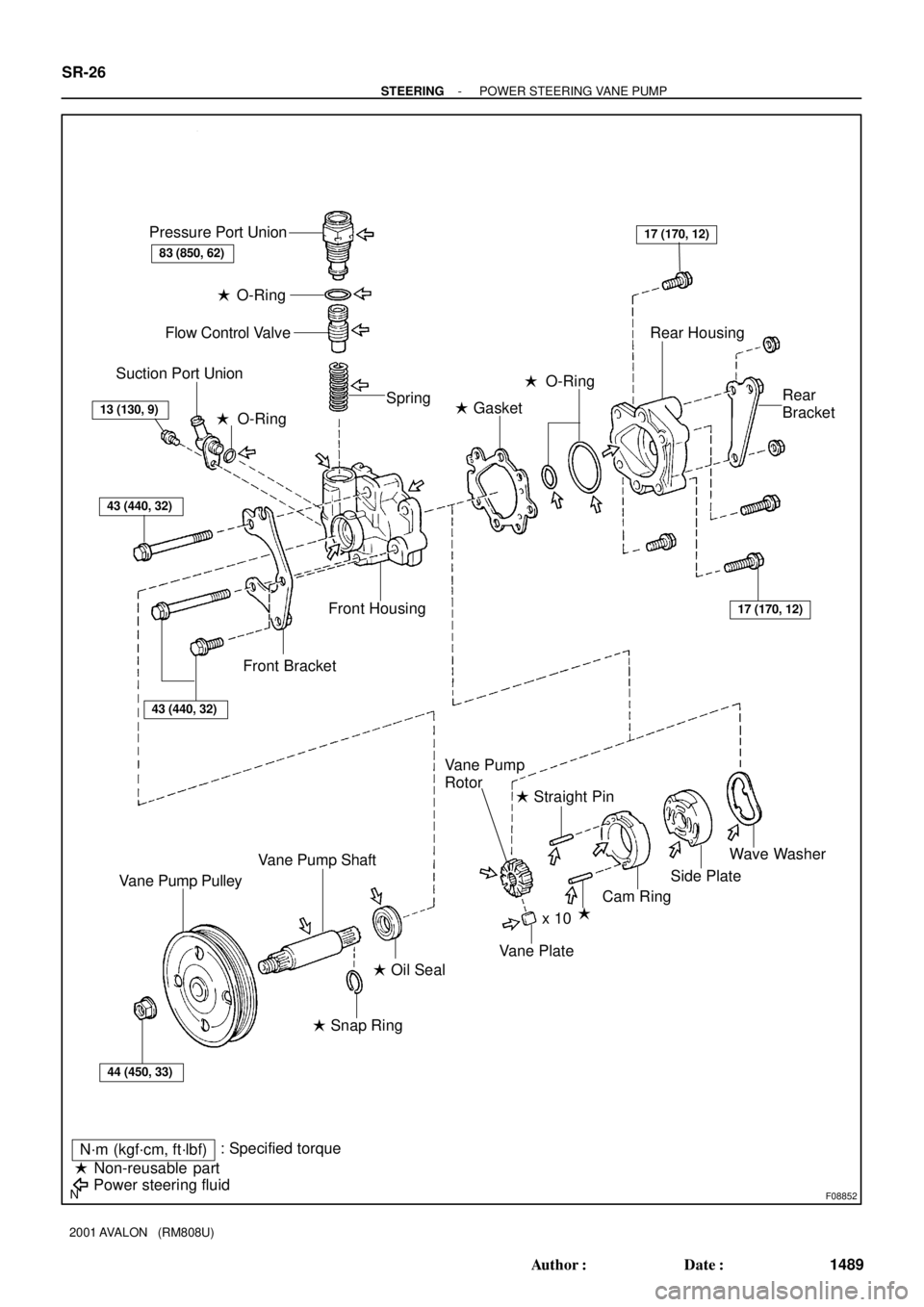
Install the pressure feed tube and gasket to the PS vane pump
assembly with union bolt.
HINT:
Make sure the stopper of the pressure feed tube touches the
front bracket as shown in the illustration, then install the union
bolt.
Torque: 52 N´m (530 kgf´cm, 38 ft´lbf)
2. INSTALL OIL PRESSURE SWITCH
Torque: 21 N´m (210 kgf´cm, 15 ft´lbf)
NOTICE:
Be careful to prevent oil seal from being attached to the
connector.
3. INSTALL PS VANE PUMP ASSEMBLY WITH PRESS-
ER FEED TUBE
Temporarily install the PS vane pump assembly with 2 (A and
B) bolts.
4. INSTALL DRIVE BELT
(a) Adjust drive belt tension (See page SR-3).
(b) Using SST, torque the bolt A.
SST 09249-63010
Torque: 29 N´m (300 kgf´cm, 22 ft´lbf)
HINT:
�Use a torque wrench with a fulcrum length of 300 mm
(11.81 in.).
�Disconnect the clamp with engine wire.
(c) Torque the bolt B.
Torque: 43 N´m (440 kgf´cm, 32 ft´lbf)
(d) Connect the connector to the oil pressure switch.
Page 1812 of 1897
SR0EO-06
F13584
Pressure Feed TubeSST
F08855
A
B
- STEERINGPOWER STEERING VANE PUMP
SR-27
1490 Author�: Date�:
2001 AVALON (RM808U)
REMOVAL
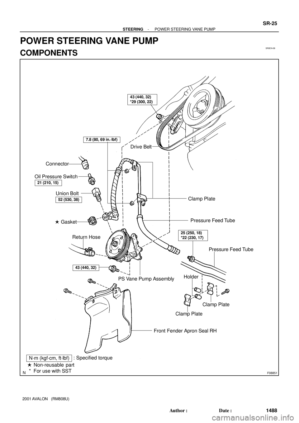
1. REMOVE FRONT FENDER APRON SEAL RH
Remove the 2 bolts and front fender apron seal RH.
2. DISCONNECT RETURN HOSE
Remove the clip and disconnect the return hose.
NOTICE:
Take care not to spill fluid on the drive belt.
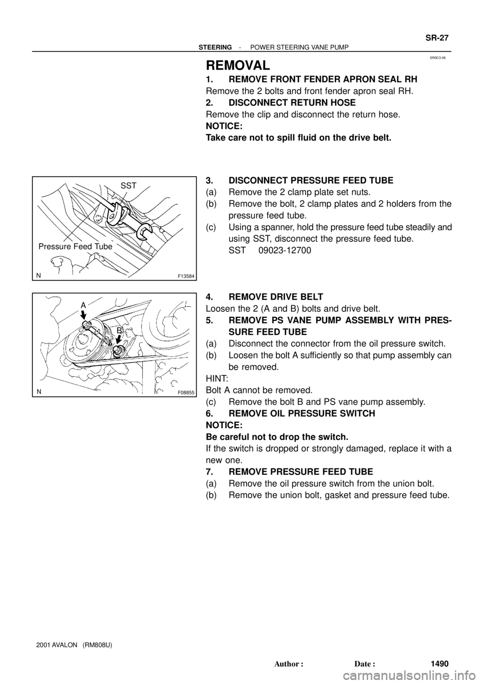
3. DISCONNECT PRESSURE FEED TUBE
(a) Remove the 2 clamp plate set nuts.
(b) Remove the bolt, 2 clamp plates and 2 holders from the
pressure feed tube.
(c) Using a spanner, hold the pressure feed tube steadily and
using SST, disconnect the pressure feed tube.
SST 09023-12700
4. REMOVE DRIVE BELT
Loosen the 2 (A and B) bolts and drive belt.
5. REMOVE PS VANE PUMP ASSEMBLY WITH PRES-
SURE FEED TUBE
(a) Disconnect the connector from the oil pressure switch.
(b) Loosen the bolt A sufficiently so that pump assembly can
be removed.
HINT:
Bolt A cannot be removed.
(c) Remove the bolt B and PS vane pump assembly.
6. REMOVE OIL PRESSURE SWITCH
NOTICE:
Be careful not to drop the switch.
If the switch is dropped or strongly damaged, replace it with a
new one.
7. REMOVE PRESSURE FEED TUBE
(a) Remove the oil pressure switch from the union bolt.
(b) Remove the union bolt, gasket and pressure feed tube.