Page 23 of 1897
I12952
Air DuctHeater Radiator
Unit Case LH
Evaporator
Unit Case RHExpansion Valve
Liquid and
Suction Tube
Air Outlet Servomotor
Air Vent Duct
Auto A/C:
Aspirator HoseDrain Hose
Evaporator Temp.
Sensor
5.4 (55, 48 in.´lbf)
N´m (kgf´cm, ft´lbf) : Specified torque
� Non-reusable part
x 10
� O-Rings
AspiratorAuto A/C:
Air Mix Servomotor
(Passenger side)
� O-Rings
Auto A/C
Air Mix Servomotor
(Driver side)
Air Duct
Plate
- AIR CONDITIONINGAIR CONDITIONING UNIT
AC-27
1949 Author�: Date�:
2001 AVALON (RM808U)
Page 144 of 1897

AX05D-03
AT3785
AT0103
D01019
Q05728
Connector AX-6
- AUTOMATIC TRANSAXLEVALVE BODY ASSEMBLY
1296 Author�: Date�:
2001 AVALON (RM808U)
VALVE BODY ASSEMBLY
ON-VEHICLE REPAIR
1. CLEAN TRANSAXLE EXTERIOR
To help prevent contamination, clean the exterior of the trans-
axle.
2. DRAIN ATF
Using a hexagon wrench, remove the drain plug and drain the
fluid into the suitable container.
3. REMOVE OIL PAN AND GASKET
NOTICE:
Some fluid will remain in the oil pan.
Remove oil pan bolts, and carefully remove the pan assembly.
Discard the gasket.
4. EXAMINE PARTICLES IN PAN
Remove the magnets and use them to collect any steel chips.
Look at the chips and particles in the pan and magnet carefully
to anticipate what type of wear you will find in the transaxle.
�Steel (magnetic): bearing, gear and plate wear
�Brass (non-magnetic): bushing wear
5. REMOVE OIL STRAINER AND APPLY PIPE BRACKET
(a) Remove the 3 bolts and oil strainer.
NOTICE:
Be careful as oil will come out of the strainer when it is re-
moved.
(b) Remove the 3 bolts and apply pipe bracket.
6. REMOVE OIL PIPE
Pry up both pipe ends with a large screwdriver and remove the
5 pipes.
7. DISCONNECT 3 SOLENOID CONNECTORS
Page 149 of 1897
Z19256
BA
B A
AT3741
AT3785
- AUTOMATIC TRANSAXLEVALVE BODY ASSEMBLY
AX-1 1
1301 Author�: Date�:
2001 AVALON (RM808U)
24. INSTALL OIL STRAINER AND APPLY PIPE BRACKET
Install the oil strainer and apply pipe bracket with the 6 bolts.
Torque:
Bolt A: 10 N´m (100 kgf´cm, 7 ft´lbf)
Bolt B: 11 N´m (110 kgf´cm, 8 ft´lbf)
Bolt length:
Bolt A: 22 mm (0.866 in.)
Bolt B: 53 mm (2.087 in.)
25. INSTALL MAGNET IN PLACE
Install the 3 magnets in the indentations of the oil pan, as shown
in the illustration.
NOTICE:
Make sure that the magnet does not interfere with the oil
pipes.
26. INSTALL OIL PAN AND GASKET
(a) Install the oil pan and a new gasket.
(b) Install the 17 bolts.
Torque: 7.8 N´m (80 kgf´cm, 69 in.´lbf)
27. INSTALL DRAIN PLUG
Install a new gasket and drain plug.
Torque: 49 N´m (500 kgf´cm, 36 ft´lbf)
28. FILL ATF AND CHECK FLUID LEVEL
(See page DI-160)
Page 465 of 1897
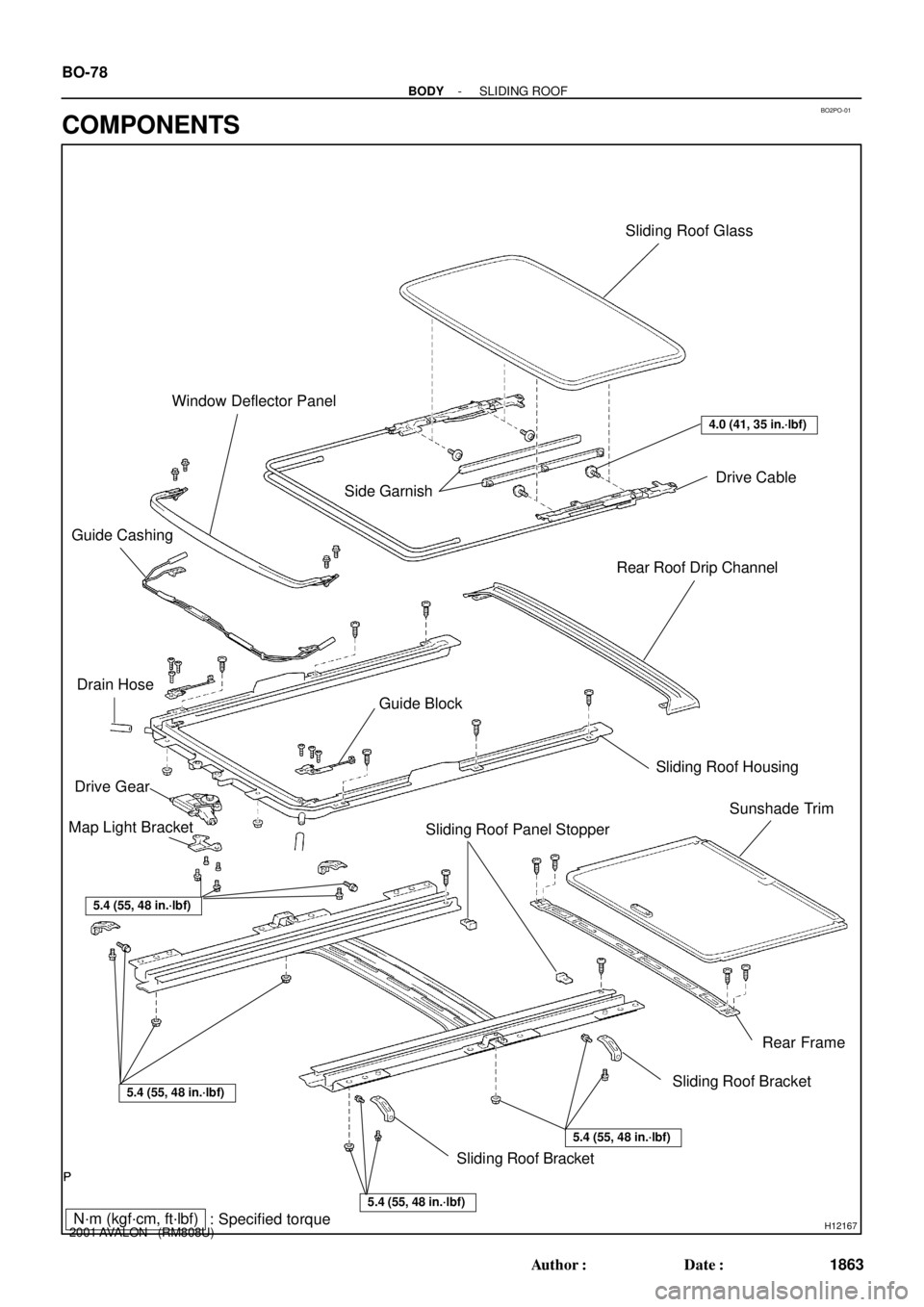
BO2PO-01
H12167
Sliding Roof Glass
Drive Cable
Side Garnish
Rear Roof Drip Channel
Guide Block Guide CashingWindow Deflector Panel
Drive Gear
Map Light Bracket
Sliding Roof Panel StopperSliding Roof Housing
Sunshade Trim
Rear Frame
Sliding Roof Bracket
Sliding Roof Bracket
5.4 (55, 48 in.´lbf)
5.4 (55, 48 in.´lbf)
5.4 (55, 48 in.´lbf)
5.4 (55, 48 in.´lbf)
4.0 (41, 35 in.´lbf)
N´m (kgf´cm, ft´lbf)
: Specified torque Drain Hose
BO-78
- BODYSLIDING ROOF
1863 Author�: Date�:
2001 AVALON (RM808U)
COMPONENTS
Page 751 of 1897

Q04874
Controlled
Pressure
Drain Controlled
Pressure Line
Pressure
Q08040D02461
(+)
(+)
(-) (-)
- DIAGNOSTICSAUTOMATIC TRANSAXLE
DI-187
343 Author�: Date�:
2001 AVALON (RM808U)
DTC P0770 Shift Solenoid E Malfunction
(Shift Solenoid Valve SL)
SYSTEM DESCRIPTION
The ECM uses the signals from the throttle position sensor, air-
flow meter and crankshaft position sensor to monitor the en-
gagement condition of the lock-up clutch.
Then the ECM compares the engagement condition of the
lock-up clutch with the lock-up schedule in the ECM memory
to detect mechanical trouble of the shift solenoid valve SL,
valve body, torque converter clutch or automatic transaxle
(clutch, brake or gear etc.).
DTC No.DTC Detecting ConditionTrouble Area
P0770
�Lock-up does not occur when driving in the lock-up range
(normal driving at 80 km/h [50 mph]), or lock-up remains ON
in the lock-up OFF range.
(2-trip detection logic)
�When lock-up is ON, clutch or brake slips or gear is broken.�Shift solenoid valve SL is stuck open or closed
�Valve body blocked up or stuck
�Lock-up clutch
�Automatic transaxle (clutch, brake or gear etc.)
INSPECTION PROCEDURE
1 Check solenoid valve SL operation.
PREPARATION:
(a) Remove the oil pan.
(b) Remove the shift solenoid valve SL.
CHECK:
(a) Applying 490 kPa (5 kgf/cm2, 71 psi) of compressed air,
check that the solenoid valve does not leak air.
(b) When battery positive voltage is supplied to the shift sole-
noid valve, check that the solenoid valve opens.
OK:
(a) Solenoid valve does not leak air.
(b) Solenoid valve opens.
NG Replace the solenoid valve SL.
OK
DI02M-08
Page 1289 of 1897
EM04B-04
A10521
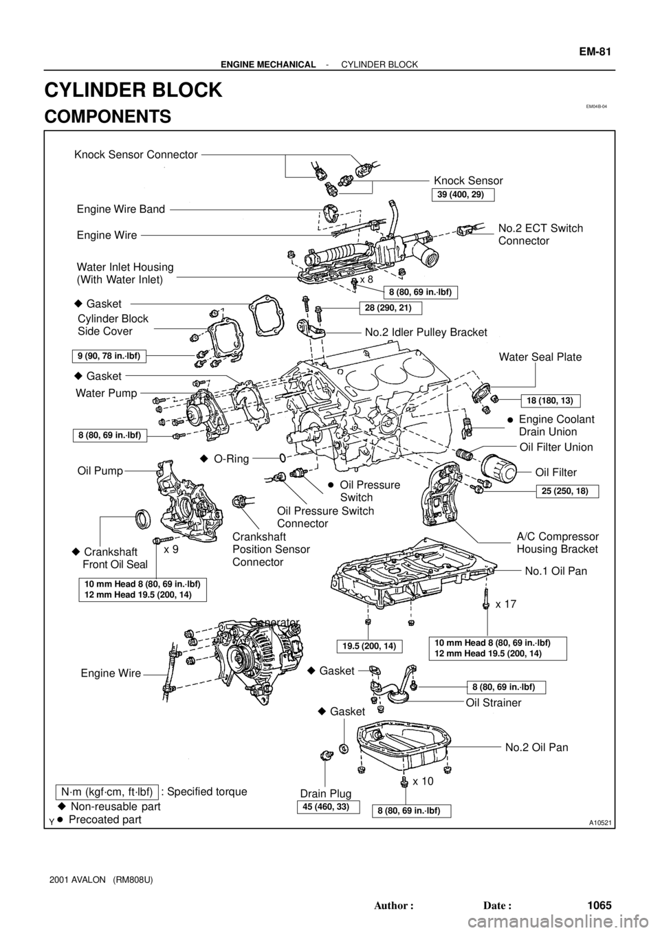
Knock Sensor Connector
Engine Wire Band
Engine WireKnock Sensor
Water Inlet Housing
(With Water Inlet)
No.2 Idler Pulley Bracket
Water Seal Plate
Engine Coolant
Drain Union
Oil Filter Union
Oil Filter � Gasket
Cylinder Block
Side Cover
� Gasket
Water Pump
� Crankshaft
Front Oil Seal
Crankshaft
Position Sensor
Connector� Oil Pressure
Switch
Oil Pressure Switch
Connector
A/C Compressor
Housing Bracket
No.1 Oil Pan
x 17 Oil Pump
� Gasket
� Gasket
Engine WireGenerator
Drain Plugx 10No.2 Oil Pan Oil Strainer
� Non-reusable part
N´m (kgf´cm, ft´lbf): Specified torque
Precoated part �
8 (80, 69 in.´lbf)
8 (80, 69 in.´lbf)
10 mm Head 8 (80, 69 in.´lbf)
12 mm Head 19.5 (200, 14)
10 mm Head 8 (80, 69 in.´lbf)
12 mm Head 19.5 (200, 14)
45 (460, 33)
8 (80, 69 in.´lbf)
9 (90, 78 in.´lbf)
x 8
8 (80, 69 in.´lbf)
28 (290, 21)
�
18 (180, 13)
25 (250, 18)
39 (400, 29)
No.2 ECT Switch
Connector
� O-Ring
x 9
19.5 (200, 14)
- ENGINE MECHANICALCYLINDER BLOCK
EM-81
1065 Author�: Date�:
2001 AVALON (RM808U)
CYLINDER BLOCK
COMPONENTS
Page 1292 of 1897
P12389
SST
A05253
P18763
WaterSeal
Plate
Oil Filter
Union
12 mm
Hexagon
Wrench
Coolant
Drain
Union
A02010
P12508
EM-84
- ENGINE MECHANICALCYLINDER BLOCK
1068 Author�: Date�:
2001 AVALON (RM808U)
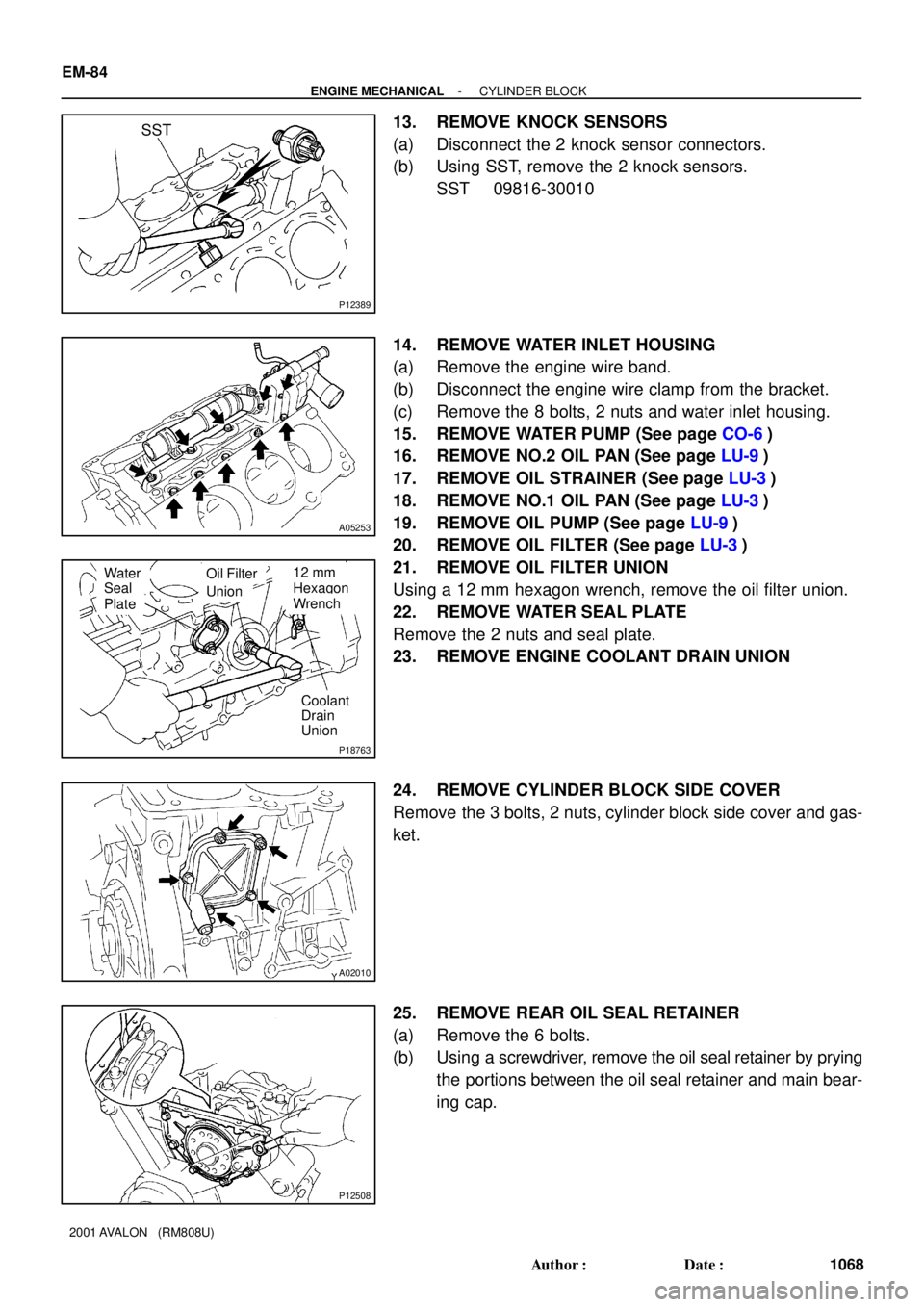
13. REMOVE KNOCK SENSORS
(a) Disconnect the 2 knock sensor connectors.
(b) Using SST, remove the 2 knock sensors.
SST 09816-30010
14. REMOVE WATER INLET HOUSING
(a) Remove the engine wire band.
(b) Disconnect the engine wire clamp from the bracket.
(c) Remove the 8 bolts, 2 nuts and water inlet housing.
15. REMOVE WATER PUMP (See page CO-6)
16. REMOVE NO.2 OIL PAN (See page LU-9)
17. REMOVE OIL STRAINER (See page LU-3)
18. REMOVE NO.1 OIL PAN (See page LU-3)
19. REMOVE OIL PUMP (See page LU-9)
20. REMOVE OIL FILTER (See page LU-3)
21. REMOVE OIL FILTER UNION
Using a 12 mm hexagon wrench, remove the oil filter union.
22. REMOVE WATER SEAL PLATE
Remove the 2 nuts and seal plate.
23. REMOVE ENGINE COOLANT DRAIN UNION
24. REMOVE CYLINDER BLOCK SIDE COVER
Remove the 3 bolts, 2 nuts, cylinder block side cover and gas-
ket.
25. REMOVE REAR OIL SEAL RETAINER
(a) Remove the 6 bolts.
(b) Using a screwdriver, remove the oil seal retainer by prying
the portions between the oil seal retainer and main bear-
ing cap.
Page 1313 of 1897
P12477
Seal Packing
Z09223
Seal Width
3 - 5 mmA
BA
B
- ENGINE MECHANICALCYLINDER BLOCK
EM-107
1091 Author�: Date�:
2001 AVALON (RM808U)
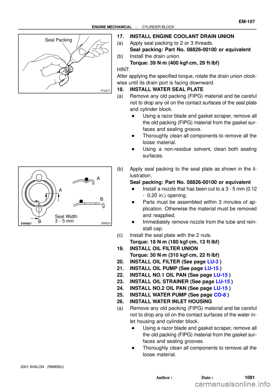
17. INSTALL ENGINE COOLANT DRAIN UNION
(a) Apply seal packing to 2 or 3 threads.
Seal packing: Part No. 08826-00100 or equivalent
(b) Install the drain union.
Torque: 39 N´m (400 kgf´cm, 29 ft´lbf)
HINT:
After applying the specified torque, rotate the drain union clock-
wise until its drain port is facing downward.
18. INSTALL WATER SEAL PLATE
(a) Remove any old packing (FIPG) material and be careful
not to drop any oil on the contact surfaces of the seal plate
and cylinder block.
�Using a razor blade and gasket scraper, remove all
the old packing (FIPG) material from the gasket sur-
faces and sealing groove.
�Thoroughly clean all components to remove all the
loose material.
�Using a non-residue solvent, clean both sealing
surfaces.
(b) Apply seal packing to the seal plate as shown in the il-
lustration.
Seal packing: Part No. 08826-00100 or equivalent
�Install a nozzle that has been cut to a 3 - 5 mm (0.12
- 0.20 in.) opening.
�Parts must be assembled within 3 minutes of ap-
plication. Otherwise the material must be removed
and reapplied.
�Immediately remove nozzle from the tube and rein-
stall cap.
(c) Install the seal plate with the 2 nuts.
Torque: 18 N´m (180 kgf´cm, 13 ft´lbf)
19. INSTALL OIL FILTER UNION
Torque: 30 N´m (310 kgf´cm, 22 ft´lbf)
20. INSTALL OIL FILTER (See page LU-3)
21. INSTALL OIL PUMP (See page LU-15)
22. INSTALL NO.1 OIL PAN (See page LU-15)
23. INSTALL OIL STRAINER (See page LU-15)
24. INSTALL NO.2 OIL PAN (See page LU-15)
25. INSTALL WATER PUMP (See page CO-8)
26. INSTALL WATER INLET HOUSING
(a) Remove any old packing (FIPG) material and be careful
not to drop any oil on the contact surfaces of the water in-
let housing and cylinder block.
�Using a razor blade and gasket scraper, remove all
the old packing (FIPG) material from the gasket sur-
faces and sealing grooves.
�Thoroughly clean all components to remove all the
loose material.