Page 742 of 1897
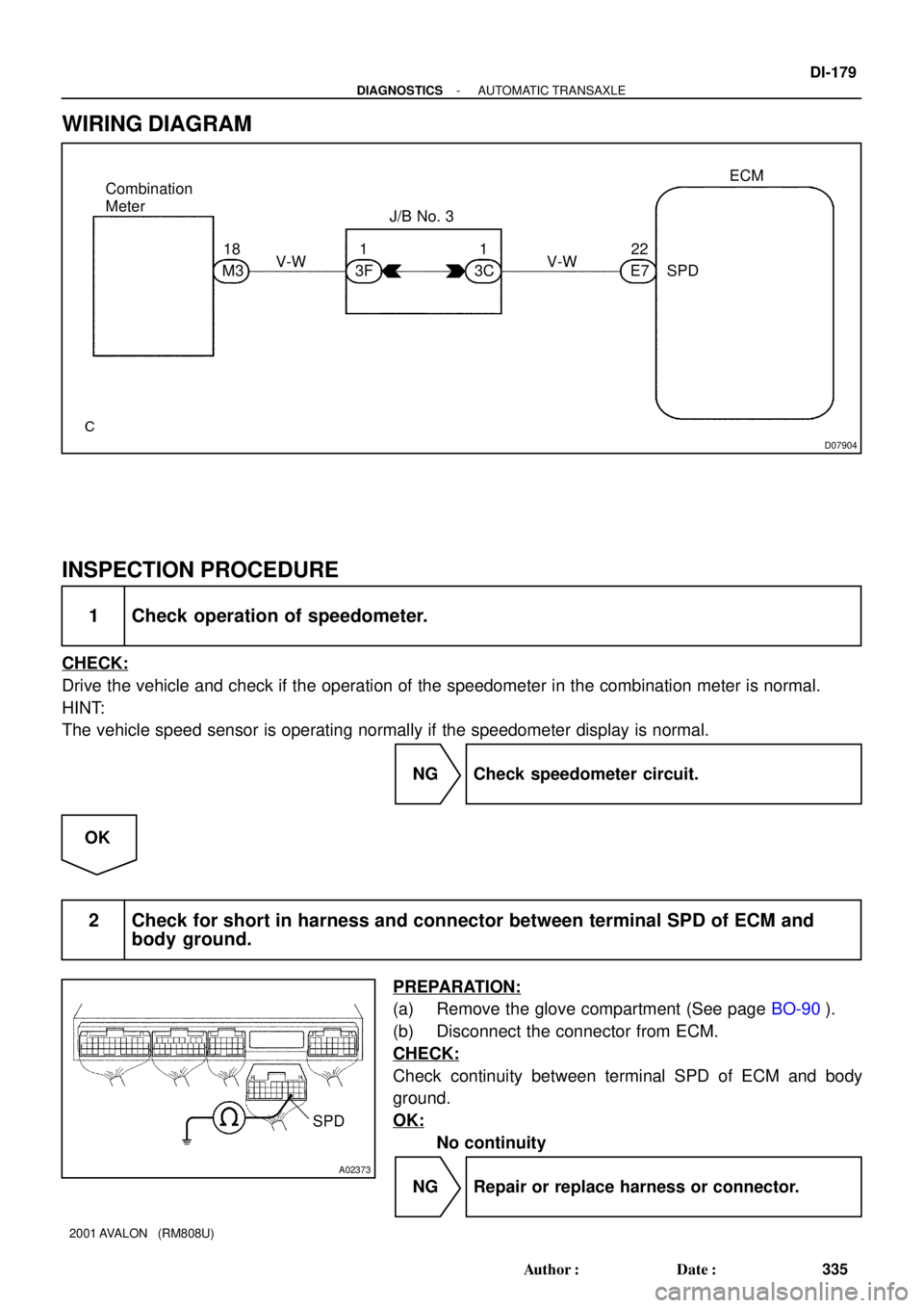
DI4DO-02
A00022
4-pulse
Combination
MeterECM 4-pulse
From
Speed SensorABS ECU DI-178
- DIAGNOSTICSAUTOMATIC TRANSAXLE
334 Author�: Date�:
2001 AVALON (RM808U)
CIRCUIT INSPECTION
DTC P0500 Vehicle Speed Sensor Malfunction
CIRCUIT DESCRIPTION
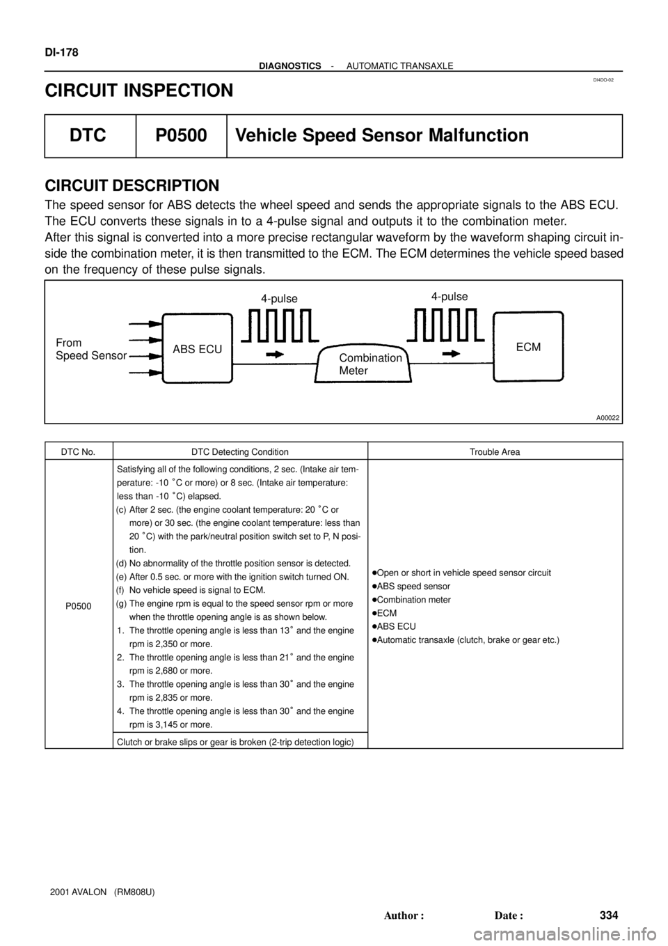
The speed sensor for ABS detects the wheel speed and sends the appropriate signals to the ABS ECU.
The ECU converts these signals in to a 4-pulse signal and outputs it to the combination meter.
After this signal is converted into a more precise rectangular waveform by the waveform shaping circuit in-
side the combination meter, it is then transmitted to the ECM. The ECM determines the vehicle speed based
on the frequency of these pulse signals.
DTC No.DTC Detecting ConditionTrouble Area
P0500
Satisfying all of the following conditions, 2 sec. (Intake air tem-
perature: -10 °C or more) or 8 sec. (Intake air temperature:
less than -10 °C) elapsed.
(c) After 2 sec. (the engine coolant temperature: 20 °C or
more) or 30 sec. (the engine coolant temperature: less than
20 °C) with the park/neutral position switch set to P, N posi-
tion.
(d) No abnormality of the throttle position sensor is detected.
(e) After 0.5 sec. or more with the ignition switch turned ON.
(f) No vehicle speed is signal to ECM.
(g) The engine rpm is equal to the speed sensor rpm or more
when the throttle opening angle is as shown below.
1. The throttle opening angle is less than 13° and the engine
rpm is 2,350 or more.
2. The throttle opening angle is less than 21° and the engine
rpm is 2,680 or more.
3. The throttle opening angle is less than 30° and the engine
rpm is 2,835 or more.
4. The throttle opening angle is less than 30° and the engine
rpm is 3,145 or more.
�Open or short in vehicle speed sensor circuit
�ABS speed sensor
�Combination meter
�ECM
�ABS ECU
�Automatic transaxle (clutch, brake or gear etc.)
Clutch or brake slips or gear is broken (2-trip detection logic)
Page 743 of 1897
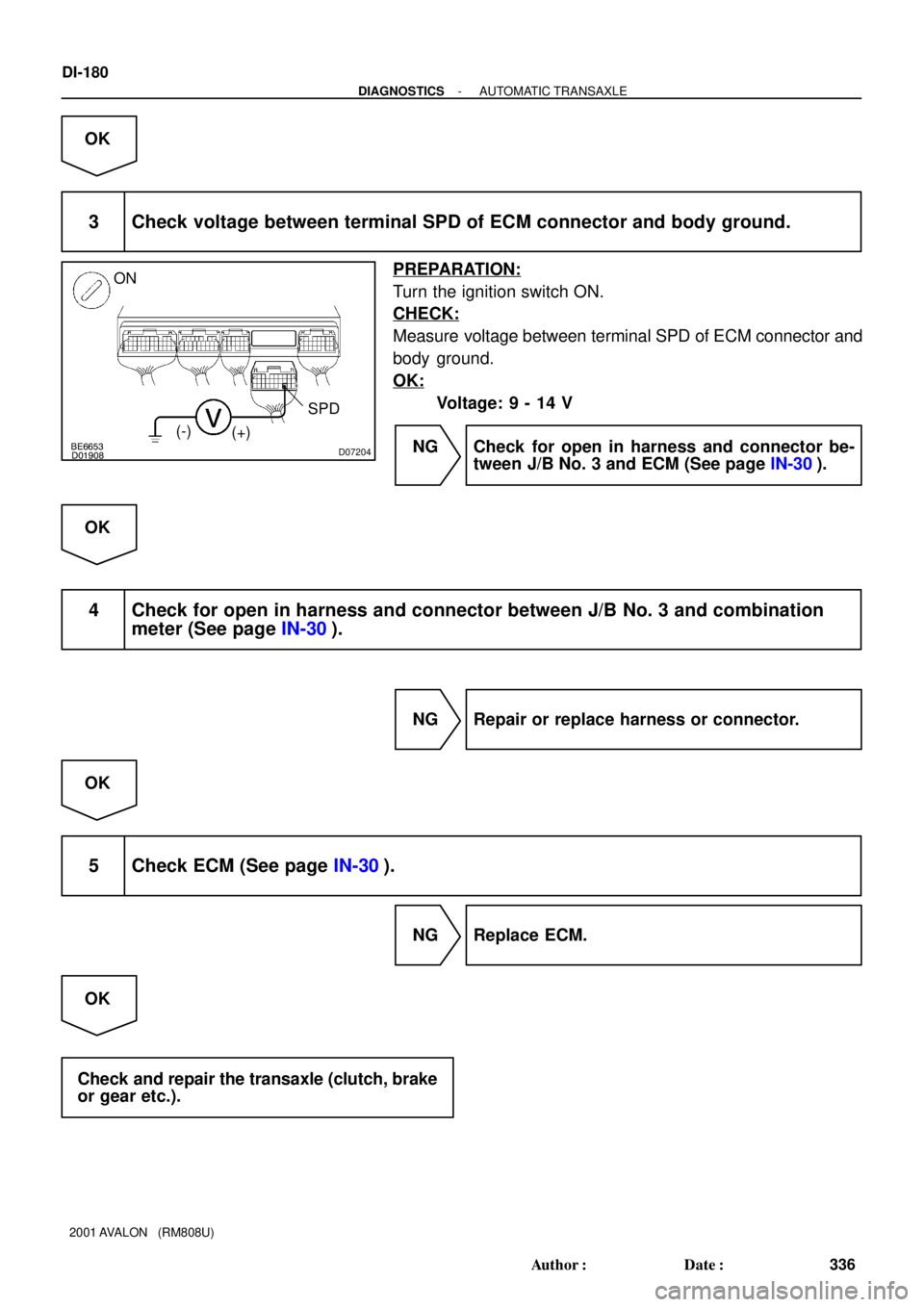
D07904
18
M3V-W22 Combination
Meter
1
3F1
3C E7ECM
SPD V-W J/B No. 3
A02373
SPD
- DIAGNOSTICSAUTOMATIC TRANSAXLE
DI-179
335 Author�: Date�:
2001 AVALON (RM808U)
WIRING DIAGRAM
INSPECTION PROCEDURE
1 Check operation of speedometer.
CHECK:
Drive the vehicle and check if the operation of the speedometer in the combination meter is normal.
HINT:
The vehicle speed sensor is operating normally if the speedometer display is normal.
NG Check speedometer circuit.
OK
2 Check for short in harness and connector between terminal SPD of ECM and
body ground.
PREPARATION:
(a) Remove the glove compartment (See page BO-90).
(b) Disconnect the connector from ECM.
CHECK:
Check continuity between terminal SPD of ECM and body
ground.
OK:
No continuity
NG Repair or replace harness or connector.
Page 744 of 1897
BE6653D01908D07204
ON
SPD
(-)
(+)
DI-180
- DIAGNOSTICSAUTOMATIC TRANSAXLE
336 Author�: Date�:
2001 AVALON (RM808U)
OK
3 Check voltage between terminal SPD of ECM connector and body ground.
PREPARATION:
Turn the ignition switch ON.
CHECK:
Measure voltage between terminal SPD of ECM connector and
body ground.
OK:
Voltage: 9 - 14 V
NG Check for open in harness and connector be-
tween J/B No. 3 and ECM (See page IN-30).
OK
4 Check for open in harness and connector between J/B No. 3 and combination
meter (See page IN-30).
NG Repair or replace harness or connector.
OK
5 Check ECM (See page IN-30).
NG Replace ECM.
OK
Check and repair the transaxle (clutch, brake
or gear etc.).
Page 764 of 1897
D07909
J5 J/C
A
A77
3A 3GW-B
P1
Park/Neutral
Position switch
W-B
2RL
2L
LLR-B
8
G-Y
3
Y
41
II1
2
II2
II2R-B
G-Y
Y18
3C
3C
3B
7
3C 3C
3D
3D 3C
GR *2
R-L
W-B20
20
15 15
FUSIBLE LINK
BLOCK
IG8
1D
1C
1B 1
1
3C9
Combination Meter
R2L
R-B G-Y
Y 25 6
16
1718 16 17
3F 3F 3G
3D
3A 3D18
16
17R-B
G-Y
Y
R-L
*1
R-L
*2
GR
*22
4D 4C11DIODE D6
3
2
1
GR
*2
ECU-ACC
GAUGE No. 2
2
410
1C
1G
1C1
4 1
3
F10
F8
F7
F6 11
1
1B-L
B2G
2G2H
2C 11
27AM2
BFL MAINBatteryB
5
1AM1
25
W-RW-L7
IF1
W-R W-L W-R W-G
4 3
IG1ACC ST2AM2
8 B-W R-L2020
E7 18
7
6R-B
G-Y
YE6
E6
E6R
2
LECM
NSW
I15
Ignition Switch
7
2 8
14
13
IG1 RELAY R-L
W
4 W-BJ/B No. 3
21
II2
II2
II2
J/B No. 3
J/B No. 3
J/B No. 4II1
Driver Side J/B
ALTEngine Room J/B Engine Room R/B No. 5
IF1 W-B*2
*1: Floor Shift
*2: Column ShiftAM1 DI-200
- DIAGNOSTICSAUTOMATIC TRANSAXLE
356 Author�: Date�:
2001 AVALON (RM808U)
WIRING DIAGRAM
Page 768 of 1897
DI02F-06
DI-172
- DIAGNOSTICSAUTOMATIC TRANSAXLE
328 Author�: Date�:
2001 AVALON (RM808U)
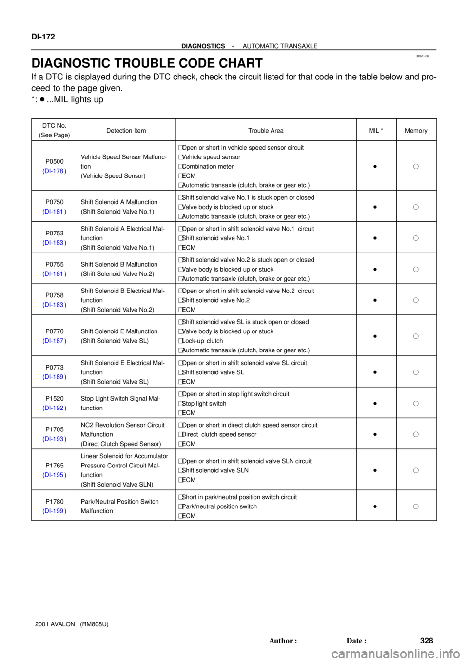
DIAGNOSTIC TROUBLE CODE CHART
If a DTC is displayed during the DTC check, check the circuit listed for that code in the table below and pro-
ceed to the page given.
*: �...MIL lights up
DTC No.
(See Page)Detection ItemTrouble AreaMIL *Memory
P0500
(DI-178)Vehicle Speed Sensor Malfunc-
tion
(Vehicle Speed Sensor)
�Open or short in vehicle speed sensor circuit
�Vehicle speed sensor
�Combination meter
�ECM
�Automatic transaxle (clutch, brake or gear etc.)
��
P0750
(DI-181)Shift Solenoid A Malfunction
(Shift Solenoid Valve No.1)�Shift solenoid valve No.1 is stuck open or closed
�Valve body is blocked up or stuck
�Automatic transaxle (clutch, brake or gear etc.)
��
P0753
(DI-183)Shift Solenoid A Electrical Mal-
function
(Shift Solenoid Valve No.1)�Open or short in shift solenoid valve No.1 circuit
�Shift solenoid valve No.1
�ECM
��
P0755
(DI-181)Shift Solenoid B Malfunction
(Shift Solenoid Valve No.2)�Shift solenoid valve No.2 is stuck open or closed
�Valve body is blocked up or stuck
�Automatic transaxle (clutch, brake or gear etc.)
��
P0758
(DI-183)Shift Solenoid B Electrical Mal-
function
(Shift Solenoid Valve No.2)�Open or short in shift solenoid valve No.2 circuit
�Shift solenoid valve No.2
�ECM
��
P0770
(DI-187)Shift Solenoid E Malfunction
(Shift Solenoid Valve SL)
�Shift solenoid valve SL is stuck open or closed
�Valve body is blocked up or stuck
�Lock-up clutch
�Automatic transaxle (clutch, brake or gear etc.)
��
P0773
(DI-189)Shift Solenoid E Electrical Mal-
function
(Shift Solenoid Valve SL)�Open or short in shift solenoid valve SL circuit
�Shift solenoid valve SL
�ECM
��
P1520
(DI-192)Stop Light Switch Signal Mal-
function�Open or short in stop light switch circuit
�Stop light switch
�ECM
��
P1705
(DI-193)NC2 Revolution Sensor Circuit
Malfunction
(Direct Clutch Speed Sensor)�Open or short in direct clutch speed sensor circuit
�Direct clutch speed sensor
�ECM
��
P1765
(DI-195)
Linear Solenoid for Accumulator
Pressure Control Circuit Mal-
function
(Shift Solenoid Valve SLN)�Open or short in shift solenoid valve SLN circuit
�Shift solenoid valve SLN
�ECM
��
P1780
(DI-199)Park/Neutral Position Switch
Malfunction�Short in park/neutral position switch circuit
�Park/neutral position switch
�ECM
��
Page 773 of 1897
FI0534
F07887
TOYOTA hand-held tester
DLC3
DI-162
- DIAGNOSTICSAUTOMATIC TRANSAXLE
318 Author�: Date�:
2001 AVALON (RM808U)
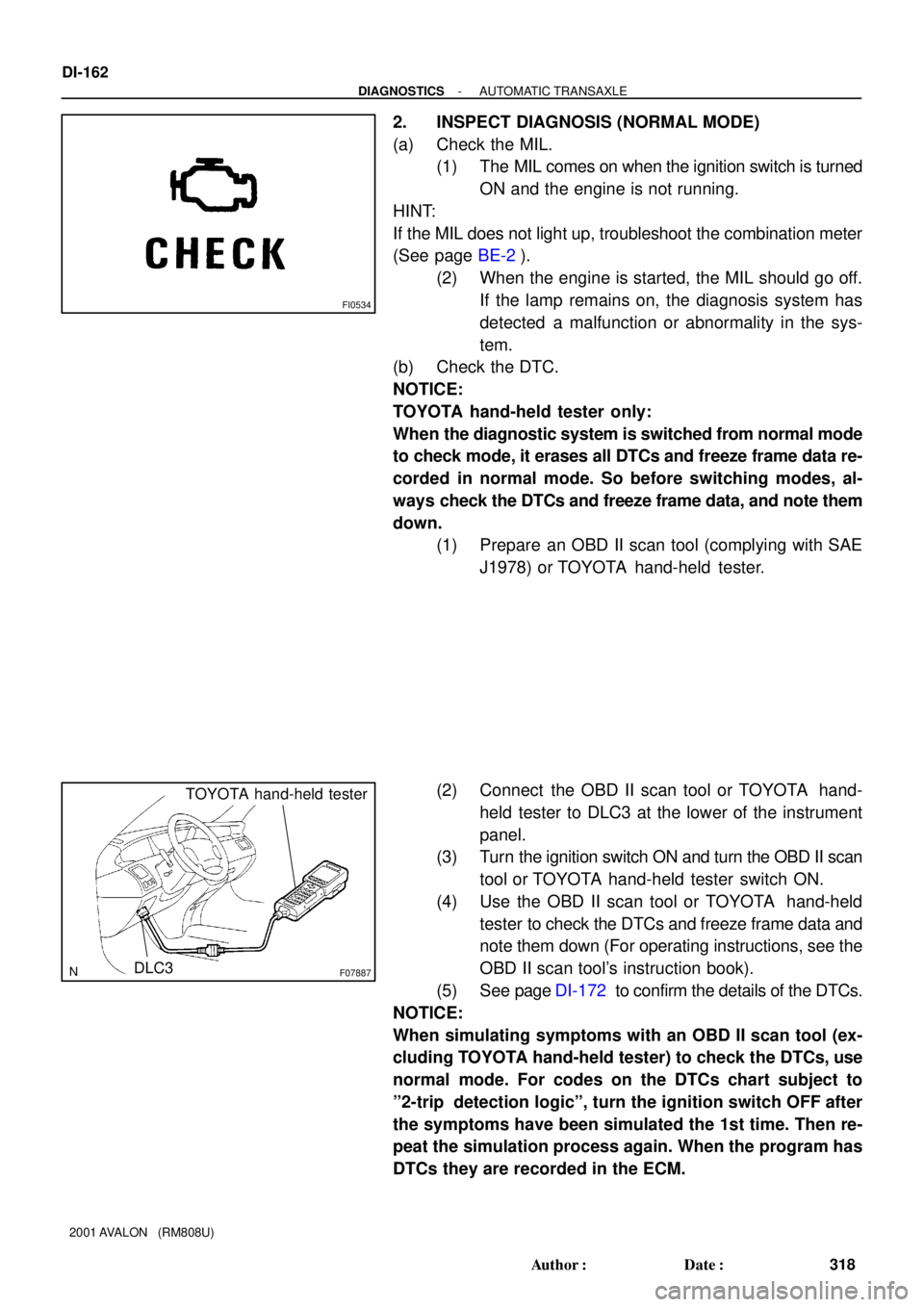
2. INSPECT DIAGNOSIS (NORMAL MODE)
(a) Check the MIL.
(1) The MIL comes on when the ignition switch is turned
ON and the engine is not running.
HINT:
If the MIL does not light up, troubleshoot the combination meter
(See page BE-2).
(2) When the engine is started, the MIL should go off.
If the lamp remains on, the diagnosis system has
detected a malfunction or abnormality in the sys-
tem.
(b) Check the DTC.
NOTICE:
TOYOTA hand-held tester only:
When the diagnostic system is switched from normal mode
to check mode, it erases all DTCs and freeze frame data re-
corded in normal mode. So before switching modes, al-
ways check the DTCs and freeze frame data, and note them
down.
(1) Prepare an OBD II scan tool (complying with SAE
J1978) or TOYOTA hand-held tester.
(2) Connect the OBD II scan tool or TOYOTA hand-
held tester to DLC3 at the lower of the instrument
panel.
(3) Turn the ignition switch ON and turn the OBD II scan
tool or TOYOTA hand-held tester switch ON.
(4) Use the OBD II scan tool or TOYOTA hand-held
tester to check the DTCs and freeze frame data and
note them down (For operating instructions, see the
OBD II scan tool's instruction book).
(5) See page DI-172 to confirm the details of the DTCs.
NOTICE:
When simulating symptoms with an OBD II scan tool (ex-
cluding TOYOTA hand-held tester) to check the DTCs, use
normal mode. For codes on the DTCs chart subject to
º2-trip detection logicº, turn the ignition switch OFF after
the symptoms have been simulated the 1st time. Then re-
peat the simulation process again. When the program has
DTCs they are recorded in the ECM.
Page 834 of 1897
DI6LG-01
BODY CONTROL SYSTEM Check Sheet
Inspector 's name:
Customer 's Name
Date VehicleRegistration No.
Registration Year
Frame No.
Odometer Reading / /km
Mile
Weather Conditions
When Problem
Occurred
Date Problem First Occurred
Frequency Problem Occurs
Weather
/ /
Once only Brought in
Key Unlock Warning System
Malfunction
System
Outdoor Temperature
Fine Cloudy Rainy Snowy
Various/ Others
Hot Warm Cool
Cold (Approx. °F ( °C))
Constant Sometimes ( times per day, month)
Illuminated Entry System
Seat Belt Warning
Power Window Control System
Power Door Lock Control System
Wireless Door Lock Control System
Others (Buzzer etc.)
Automatic Light Control System
Luggage Compartment Door Opener System
Headlight and Taillight System (Light Auto Turn-of f system Daytime Running Light
System)
Combination Meter
Auto Lock/Unlock System
Theft Deterrent System DI-616
- DIAGNOSTICSBODY CONTROL SYSTEM
772 Author�: Date�:
2001 AVALON (RM808U)
CUSTOMER PROBLEM ANALYSIS CHECK
Page 840 of 1897

DI-624
- DIAGNOSTICSBODY CONTROL SYSTEM
780 Author�: Date�:
2001 AVALON (RM808U)
INTERIOR LIGHT SYSTEM:
SymptomSuspect AreaSee page
Only one light does not light up.1. Bulb
2. Wire harness-
IN-30
Room light does not light up (All).
1. DOME fuse
2. Body ECU
3. Wire harnessBE-9
IN-30
IN-30
Room light does not light up (Room light only).
1. Bulb
2. Room light assembly
3. Wire harness-
BE-31
IN-30
ºIlluminated Entry Systemº does not operate.
1. Illumination circuit
2. Door courtesy switch circuit
3. Door unlock detection switch circuit
4. Body ECU
5. Wire harnessDI-655
DI-639
DI-643
DI-686
DI-708
IN-30
IN-30
Front personal light does not light up.
1. Bulb
2. Front personal light
3. Body ECU
4. Wire harness-
BE-31
IN-30
IN-30
Rear personal light does not light up.1. Bulb
2. Rear personal light-
BE-31
Vanity light does not light up.
1. Bulb
2. Vanity light
3. Wire harness-
BE-31
IN-30
Luggage room light does not light up.
1. Bulb
2. Luggage compartment light
3. Luggage compartment door courtesy switch circuit
4. Body ECU
5. Wire harness-
BE-31
BE-31
IN-30
IN-30
COMBINATION METER:
SymptomSuspect AreaSee page
Seat Belt warning light does not light up.
1. Warning light bulb
2. Buckle switch circuit
3. Body ECU
4. Meter circuit plate
5. Wire harnessBE-43
BE-53
IN-30
BE-43
IN-30
Open Door warning light does not light up.
1. DOME fuse
2. Warning light bulb
3. Door courtesy switch circuit
4. Illumination circuit
5. Meter circuit plate
6. Wire harnessBE-9
BE-43
DI-639
DI-655
BE-43
IN-30