Page 308 of 1897

BE-4
- BODY ELECTRICALTROUBLESHOOTING
1608 Author�: Date�:
2001 AVALON (RM808U)
COMBINATION METER (Meter, Gauges and Illumination):
SymptomSuspect AreaSee page
Tachometer, Fuel Gauge and Engine Coolant Temperature Gauge
do not operate.
1. ECU-B Fuse
2. ECU-IG No. 2 Fuse
3. Meter Circuit Plate
4. Wire Harness
5. Multi Display-
-
BE-43
-
-
Speedometer does not operate.
1. Vehicle Speed Sensor (ABS - ECU)
2. Meter Circuit Plate
3. Wire Harness
4. Multi DisplayBE-53
BE-43
-
-
Tachometer does not operate.
1. EFI - ECU
2. Meter Circuit Plate
3. Wire Harness
4. Multi Display-
BE-43
-
-
Fuel Gauge does not operate or abnormal operation.
1. Fuel Receiver Gauge
2. Fuel Sender Gauge
3. Meter Circuit Plate
4. Wire HarnessBE-53
BE-53
BE-43
-
Engine Coolant Temperature Gauge does not operate or abnormal
operation.
1. Engine Coolant Temperature Receiver Gauge
2. Engine Coolant Temperature Sender Gauge
3. Meter Circuit Plate
4. Wire HarnessBE-53
BE-53
BE-43
-
All illumination lights do not light up.
1. Bulb
2. PANEL Fuse
3. Light Control Rheostat
4. Wire Harness-
-
BE-53
-
Brightness does not change even when rheostat turned.
1. Bulb
2. Rheostat
3. Wire Harness-
-
-
Only one illumination light does not light up.1. Bulb
2. Wire Harness-
-
COMBINATION METER (Warning Lights):
SymptomSuspect AreaSee page
Warning lights do not light up. (Except Discharge, Open Door and
SRS)
1. Bulb
2. GAUGE No. 1 Fuse
3. Meter Circuit Plate
4. Wire Harness-
-
BE-53
-
Low Oil Pressure warning light does not light up.
1. Multi Display
2. Bulb
3. Low Oil Pressure Warning Switch
4. Meter Circuit Plate
5. Wire Harness-
-
BE-53
BE-43
-
Fuel Level warning light does not light up.
1. Multi Display
2. Bulb
3. Fuel Sender Gause
4. Meter Circuit Plate
5. Wire Harness-
-
BE-53
BE-43
-
ABS warning light does not light up.
1. Bulb
2. ABS ECU
3. Wire Harness-
DI-210
-
Page 309 of 1897

- BODY ELECTRICALTROUBLESHOOTING
BE-5
1609 Author�: Date�:
2001 AVALON (RM808U) Seat Belt warning light does not light up.
1. Bulb
2. Body Control System
3. Meter Circuit Plate
4. Wire Harness-
DI-615
BE-53
-
Discharge warning light does not light up.
1. AM2 - Fuse
2. Bulb
3. Meter Circuit Plate
4. Wire Harness
5. Generator-
-
BE-53
-
CH-9
Light Failure warning light does not light up.
1. Bulb
2. Light Failure Sensor
3. Bulb Check Relay
4. Wire Harness
5. Taillight System-
BE-53
BE-53
-
BE-2
Brake warning light does not light up.
1. Bulb
2. Parking Brake Switch
3. Brake Fluid Level Warning Switch
4. Bulb Check Relay
5. Meter Circuit Plate
6. Wire Harness-
BE-53
BE-53
BE-53
BE-43
-
SRS Warning light does not light up.
1. AM2 - Fuse
2. Bulb
3. Airbag Sensor Assembly
4. Meter Circuit Plate
5. Wire Harness-
-
RS-62
RS-67
BE-43
Open Door warning light does not light up.
1. DOME Fuse
2. Bulb
3. Door Courtesy Switch
4. Body Control System
5. Meter Circuit Plate
6. Wire Harness-
-
BE-31
DI-615
BE-43
-
Washer Level warning light does not light up.
1. Bulb
2. Washer Fluid Level Warning Switch
3. Meter Circuit Plate
4. Wire Harness-
BE-53
BE-43
-
COMBINATION METER (Indicator Lights):
SymptomSuspect AreaSee page
O/D OFF indicator light does not light up.
1. Bulb
2. O/D OFF Switch
3. ECM
4. Meter Circuit Plate
5. Wire Harness-
DI-203
DI-1
BE-43
-
Cruise Control indicator light does not light up.
1. Bulb
2. Cruise Control ECU
3. Meter Circuit Plate
4. Wire Harness-
DI-549
BE-43
-
High beam indicator light does not light up.
1. Bulb and Taillight
2. Headlight System
3. Meter Circuit Plate
4. Wire Harness-
BE-2
BE-43
-
Turn indicator light does not light up.
1. Bulb
2. Turn Signal and Hazard Warning System
3. Meter Circuit Plate
4. Wire Harness-
BE-2
BE-43
-
Page 377 of 1897
BO2PU-02
H12194: Specified torqueN´m (kgf´cm, ft´lbf)
AA
KK
K
K
K
K
K
K
B
L
E
G
GG
G
GG
G
GGI
C
C
C
C
K
K
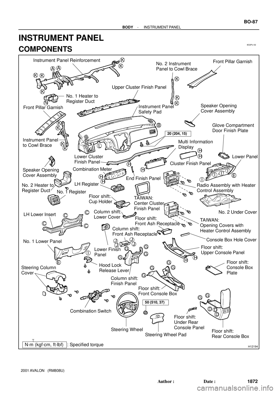
KKB Instrument Panel Reinforcement
No. 2 Instrument
Panel to Cowl BraceFront Pillar Garnish
Upper Cluster Finish Panel
Instrument Panel
Safety Pad Front Pillar GarnishNo. 1 Heater to
Register Duct
Instrument Panel
to Cowl BraceSpeaker Opening
Cover Assembly
H
H
H
H
H
H
III
G
D EDD
Steering Wheel
Floor shift:
Rear Console Box Floor shift:
Front Console Box
Combination Switch No. 1 Lower PanelLH Lower Insert
Column shift:
Finish Panel Hood Lock
Release LeverNo. 2 Under Cover
Floor shift:
Console Box
Plate
Steering Wheel Pad Steering Column
Cover
Floor shift:
Front Ash Receptacle
Floor shift:
Upper Console PanelLower Finish
Panel Column shift:
Lower Cover LH Register
TAIWAN:
Center Cluster
Finish Panel
TAIWAN:
Opening Covers with
Heater Control Assembly Radio Assembly with Heater
Control AssemblyLower Panel
Cluster Finish Panel
End Finish Panel Combination Meter Lower Cluster
Finish PanelGlove Compartment
Door Finish Plate
Speaker Opening
Cover Assembly
No. 2 Heater to
Register Duct
No. 1 Register
Floor shift:
Cup Holder
Multi Information
Display
Floor shift:
Under Rear
Console Panel
I
HH
50 (510, 37)
20 (204, 15)
N
JJJJConsole Box Hole Cover
Column shift:
Front Ash Receptacle
- BODYINSTRUMENT PANEL
BO-87
1872 Author�: Date�:
2001 AVALON (RM808U)
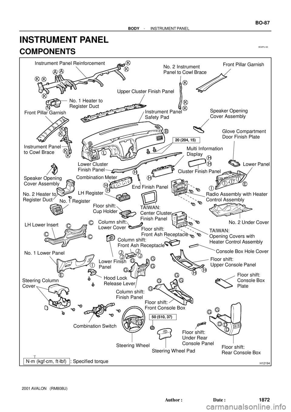
INSTRUMENT PANEL
COMPONENTS
Page 387 of 1897
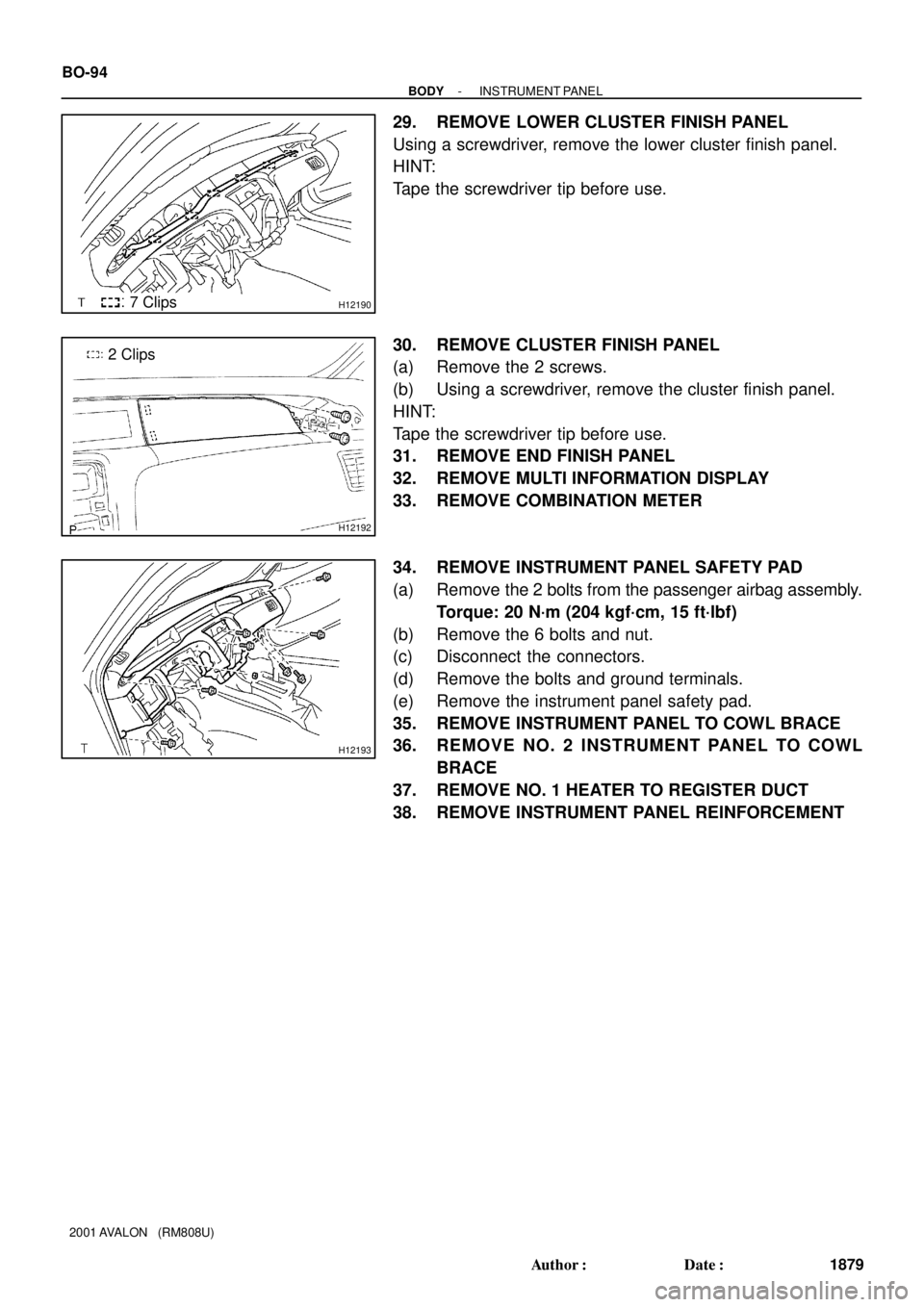
H121907 Clips
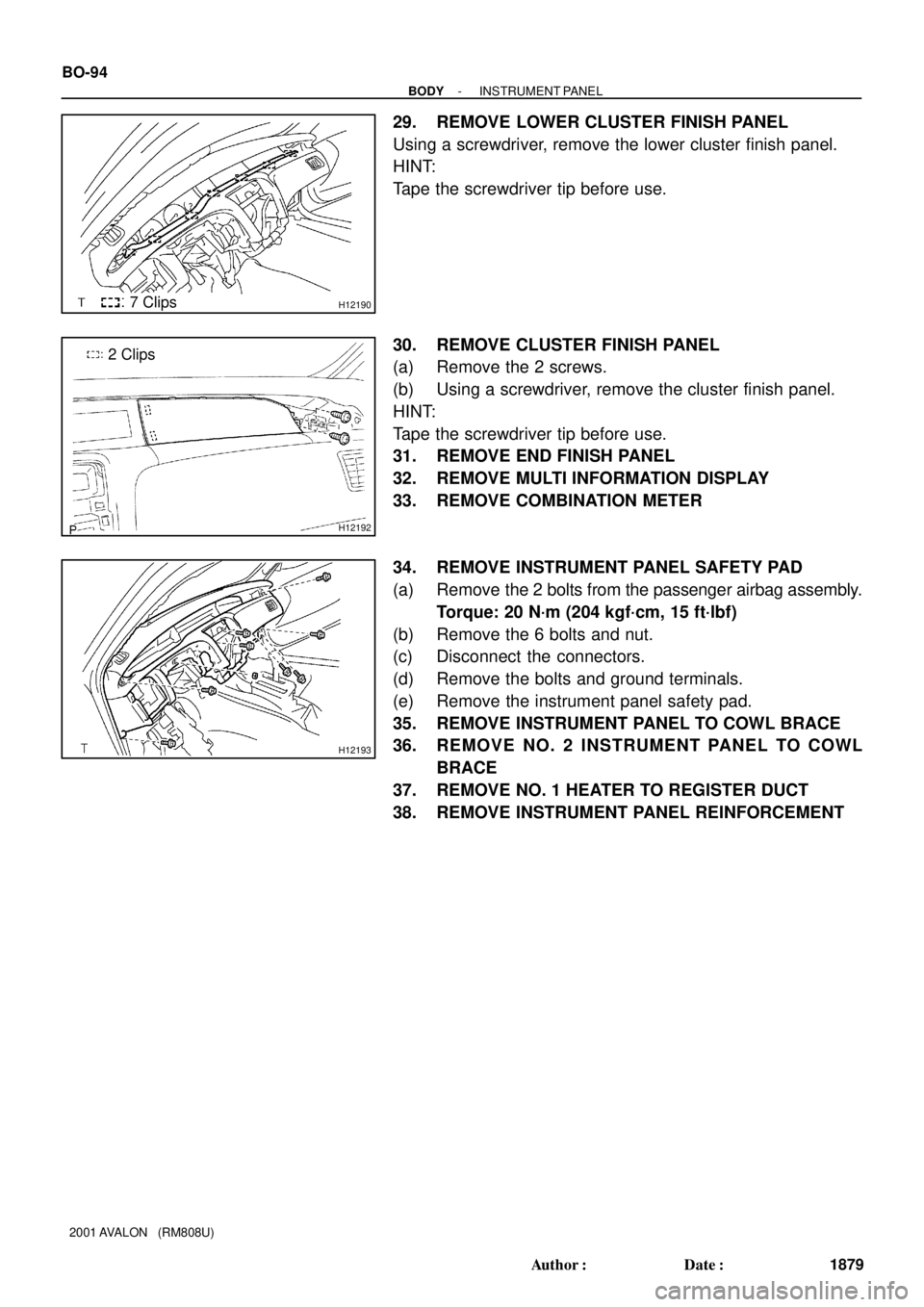
H12192
2 Clips
H12193
BO-94
- BODYINSTRUMENT PANEL
1879 Author�: Date�:
2001 AVALON (RM808U)
29. REMOVE LOWER CLUSTER FINISH PANEL
Using a screwdriver, remove the lower cluster finish panel.
HINT:
Tape the screwdriver tip before use.
30. REMOVE CLUSTER FINISH PANEL
(a) Remove the 2 screws.
(b) Using a screwdriver, remove the cluster finish panel.
HINT:
Tape the screwdriver tip before use.
31. REMOVE END FINISH PANEL
32. REMOVE MULTI INFORMATION DISPLAY
33. REMOVE COMBINATION METER
34. REMOVE INSTRUMENT PANEL SAFETY PAD
(a) Remove the 2 bolts from the passenger airbag assembly.
Torque: 20 N´m (204 kgf´cm, 15 ft´lbf)
(b) Remove the 6 bolts and nut.
(c) Disconnect the connectors.
(d) Remove the bolts and ground terminals.
(e) Remove the instrument panel safety pad.
35. REMOVE INSTRUMENT PANEL TO COWL BRACE
36. RE MO V E NO . 2 INS TRUME NT PANE L TO CO WL
BRACE
37. REMOVE NO. 1 HEATER TO REGISTER DUCT
38. REMOVE INSTRUMENT PANEL REINFORCEMENT
Page 388 of 1897
BO2PU-02
H12194: Specified torqueN´m (kgf´cm, ft´lbf)
AA
KK
K
K
K
K
K
K
B
L
E
G
GG
G
GG
G
GGI
C
C
C
C
K
K
KKB Instrument Panel Reinforcement
No. 2 Instrument
Panel to Cowl BraceFront Pillar Garnish
Upper Cluster Finish Panel
Instrument Panel
Safety Pad Front Pillar GarnishNo. 1 Heater to
Register Duct
Instrument Panel
to Cowl BraceSpeaker Opening
Cover Assembly
H
H
H
H
H
H
III
G
D EDD
Steering Wheel
Floor shift:
Rear Console Box Floor shift:
Front Console Box
Combination Switch No. 1 Lower PanelLH Lower Insert
Column shift:
Finish Panel Hood Lock
Release LeverNo. 2 Under Cover
Floor shift:
Console Box
Plate
Steering Wheel Pad Steering Column
Cover
Floor shift:
Front Ash Receptacle
Floor shift:
Upper Console PanelLower Finish
Panel Column shift:
Lower Cover LH Register
TAIWAN:
Center Cluster
Finish Panel
TAIWAN:
Opening Covers with
Heater Control Assembly Radio Assembly with Heater
Control AssemblyLower Panel
Cluster Finish Panel
End Finish Panel Combination Meter Lower Cluster
Finish PanelGlove Compartment
Door Finish Plate
Speaker Opening
Cover Assembly
No. 2 Heater to
Register Duct
No. 1 Register
Floor shift:
Cup Holder
Multi Information
Display
Floor shift:
Under Rear
Console Panel
I
HH
50 (510, 37)
20 (204, 15)
N
JJJJConsole Box Hole Cover
Column shift:
Front Ash Receptacle
- BODYINSTRUMENT PANEL
BO-87
1872 Author�: Date�:
2001 AVALON (RM808U)
INSTRUMENT PANEL
COMPONENTS
Page 398 of 1897
H121907 Clips
H12192
2 Clips
H12193
BO-94
- BODYINSTRUMENT PANEL
1879 Author�: Date�:
2001 AVALON (RM808U)
29. REMOVE LOWER CLUSTER FINISH PANEL
Using a screwdriver, remove the lower cluster finish panel.
HINT:
Tape the screwdriver tip before use.
30. REMOVE CLUSTER FINISH PANEL
(a) Remove the 2 screws.
(b) Using a screwdriver, remove the cluster finish panel.
HINT:
Tape the screwdriver tip before use.
31. REMOVE END FINISH PANEL
32. REMOVE MULTI INFORMATION DISPLAY
33. REMOVE COMBINATION METER
34. REMOVE INSTRUMENT PANEL SAFETY PAD
(a) Remove the 2 bolts from the passenger airbag assembly.
Torque: 20 N´m (204 kgf´cm, 15 ft´lbf)
(b) Remove the 6 bolts and nut.
(c) Disconnect the connectors.
(d) Remove the bolts and ground terminals.
(e) Remove the instrument panel safety pad.
35. REMOVE INSTRUMENT PANEL TO COWL BRACE
36. RE MO V E NO . 2 INS TRUME NT PANE L TO CO WL
BRACE
37. REMOVE NO. 1 HEATER TO REGISTER DUCT
38. REMOVE INSTRUMENT PANEL REINFORCEMENT
Page 599 of 1897
DI-244- DIAGNOSTICSANTI-LOCK BRAKE SYSTEM WITH ELECTRONIC
BRAKE FORCE DISTRIBUTION (EBD)
400 Author�: Date�:
2001 AVALON (RM808U)
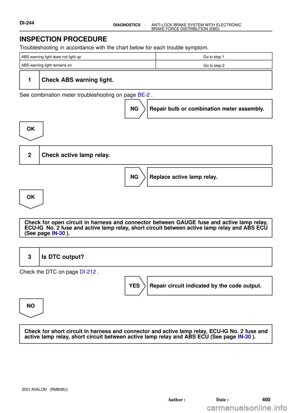
INSPECTION PROCEDURE
Troubleshooting in accordance with the chart below for each trouble symptom.
ABS warning light does not light upGo to step 1
ABS warning light remains onGo to step 2
1 Check ABS warning light.
See combination meter troubleshooting on page BE-2.
NG Repair bulb or combination meter assembly.
OK
2 Check active lamp relay.
NG Replace active lamp relay.
OK
Check for open circuit in harness and connector between GAUGE fuse and active lamp relay,
ECU-IG No. 2 fuse and active lamp relay, short circuit between active lamp relay and ABS ECU
(See page IN-30).
3 Is DTC output?
Check the DTC on page DI-212.
YES Repair circuit indicated by the code output.
NO
Check for short circuit in harness and connector and active lamp relay, ECU-IG No. 2 fuse and
active lamp relay, short circuit between active lamp relay and ABS ECU (See page IN-30).
Page 601 of 1897
- DIAGNOSTICSANTI-LOCK BRAKE SYSTEM WITH ELECTRONIC
BRAKE FORCE DISTRIBUTION (EBD)DI-239
395 Author�: Date�:
2001 AVALON (RM808U)
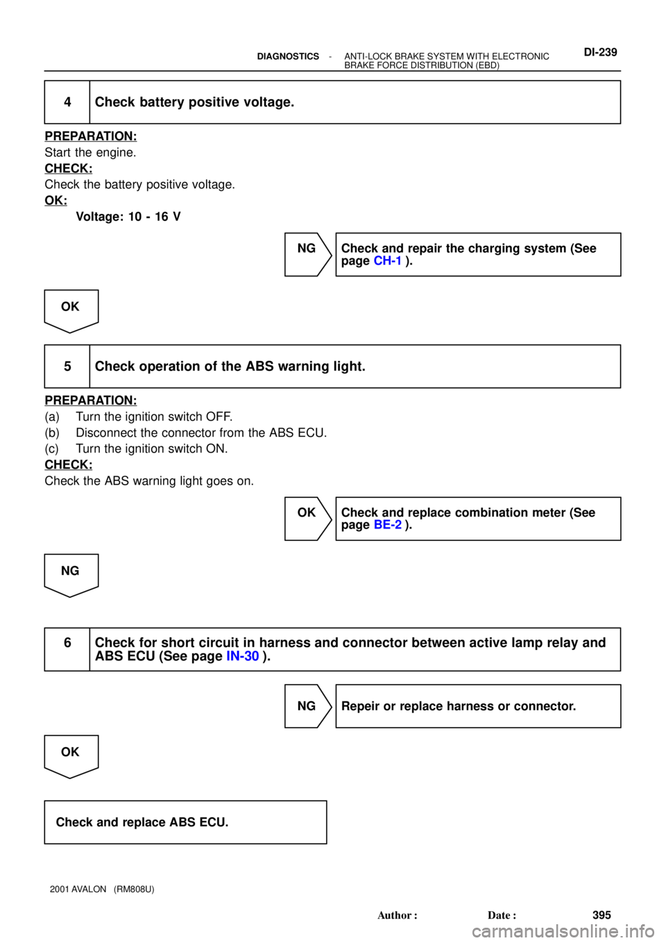
4 Check battery positive voltage.
PREPARATION:
Start the engine.
CHECK:
Check the battery positive voltage.
OK:
Voltage: 10 - 16 V
NG Check and repair the charging system (See
page CH-1).
OK
5 Check operation of the ABS warning light.
PREPARATION:
(a) Turn the ignition switch OFF.
(b) Disconnect the connector from the ABS ECU.
(c) Turn the ignition switch ON.
CHECK:
Check the ABS warning light goes on.
OK Check and replace combination meter (See
page BE-2).
NG
6 Check for short circuit in harness and connector between active lamp relay and
ABS ECU (See page IN-30).
NG Repeir or replace harness or connector.
OK
Check and replace ABS ECU.