Page 601 of 1897
- DIAGNOSTICSANTI-LOCK BRAKE SYSTEM WITH ELECTRONIC
BRAKE FORCE DISTRIBUTION (EBD)DI-239
395 Author�: Date�:
2001 AVALON (RM808U)
4 Check battery positive voltage.
PREPARATION:
Start the engine.
CHECK:
Check the battery positive voltage.
OK:
Voltage: 10 - 16 V
NG Check and repair the charging system (See
page CH-1).
OK
5 Check operation of the ABS warning light.
PREPARATION:
(a) Turn the ignition switch OFF.
(b) Disconnect the connector from the ABS ECU.
(c) Turn the ignition switch ON.
CHECK:
Check the ABS warning light goes on.
OK Check and replace combination meter (See
page BE-2).
NG
6 Check for short circuit in harness and connector between active lamp relay and
ABS ECU (See page IN-30).
NG Repeir or replace harness or connector.
OK
Check and replace ABS ECU.
Page 618 of 1897
F09798
Battery W-B
W-BGND1ABS Actuator
and ECU
A715
EE EDY-R
IG1
W-R
ALT
AM1 Driver Side J/B
IG1 RelayECU-IG
No. 2
A719
GND2
A716 1H2
1C4 2
3 1
4 1G1
1B3
W42Ignition Switch
W-L
7IF1
W-L
5
52
1
BEngine Room R/B No. 5
FL Block Engine Room J/B
2H1
2G1
2F4
2F10 B-L
W-B F61
F81
F101
B
FL MAIN IGIG1 AM1
W-B
- DIAGNOSTICSANTI-LOCK BRAKE SYSTEM WITH ELECTRONIC
BRAKE FORCE DISTRIBUTION (EBD)DI-231
387 Author�: Date�:
2001 AVALON (RM808U)
DTC 41 Power Source Circuit
CIRCUIT DESCRIPTION
This is the power source for the ECU, hence the actuators.
DTC No.DTC Detecting ConditionTrouble Area
41
At a vehicle speed of about 6 km/h (4 mph), low battery
voltage is less than 9.4 V during non-operation of ABS
control or less than 8.8 V during operation of ABS control,
and high battery voltage is more than 17.4 V.�Battery
�Charging system
�Power source circuit
WIRING DIAGRAM
DI6NH-01
Page 619 of 1897
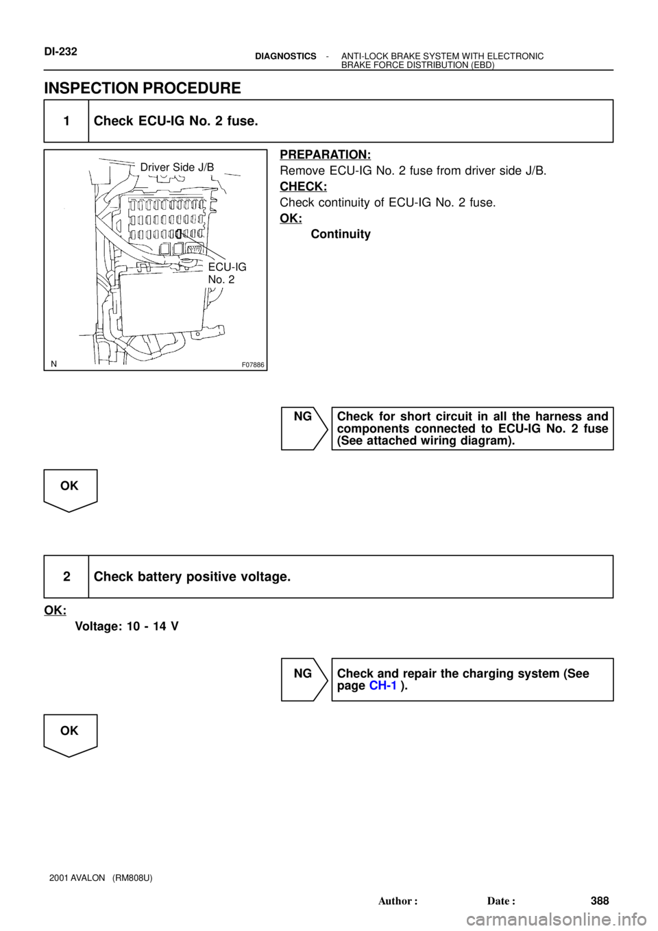
F07886
Driver Side J/B
ECU-IG
No. 2
DI-232- DIAGNOSTICSANTI-LOCK BRAKE SYSTEM WITH ELECTRONIC
BRAKE FORCE DISTRIBUTION (EBD)
388 Author�: Date�:
2001 AVALON (RM808U)
INSPECTION PROCEDURE
1 Check ECU-IG No. 2 fuse.
PREPARATION:
Remove ECU-IG No. 2 fuse from driver side J/B.
CHECK:
Check continuity of ECU-IG No. 2 fuse.
OK:
Continuity
NG Check for short circuit in all the harness and
components connected to ECU-IG No. 2 fuse
(See attached wiring diagram).
OK
2 Check battery positive voltage.
OK:
Voltage: 10 - 14 V
NG Check and repair the charging system (See
page CH-1).
OK
Page 630 of 1897
DI-215
371 Author�: Date�:
2001 AVALON (RM808U)
DIAGNOSTIC TROUBLE CODE CHART
HINT:
�Using SST 09843-18020")
DI6N8-01
- DIAGNOSTICSANTI-LOCK BRAKE SYSTEM WITH ELECTRONIC
BRAKE FORCE DISTRIBUTION (EBD)DI-215
371 Author�: Date�:
2001 AVALON (RM808U)
DIAGNOSTIC TROUBLE CODE CHART
HINT:
�Using SST 09843-18020, connect the terminals Tc and E1.
�If any abnormality is found when inspecting parts, inspect the ECU.
�If a malfunction code is displayed during the DTC check, check the circuit listed under the code. For
details of each code, refer to the page under respective ºDTC No.º in the DTC chart.
DTC No.
(See Page)Detection ItemTrouble Area
11
(DI-219)Open or short circuit in ABS solenoid relay circuit�ABS solenoid relay
�ABS solenoid relay circuit
13
(DI-221)Open or short circuit in ABS pump motor circuit�ABS motor relay
�ABS motor relay circuit
21
(DI-223)Open or short circuit in brake actuator�Brake actuator
�SFRR or SFRH circuit
22
(DI-223)Open or short circuit in brake actuator�Brake actuator
�SFLR or SFLH circuit
23
(DI-223)Open or short circuit in brake actuator�Brake actuator
�SRRR or SRRH circuit
24
(DI-223)Open or short circuit in brake actuator�Brake actuator
�SRLR or SRLH circuit
31*
(DI-225)Right front wheel speed sensor signal malfunction
32*
(DI-225)Left front wheel speed sensor signal malfunction�Right front, left front, right rear and left rear speed sensor
Eh d i it33*
(DI-225)Right rear wheel speed sensor signal malfunction
�Each speed sensor circuit
�Sensor installation
34*
(DI-225)Left rear wheel speed sensor signal malfunction
35*
(DI-225)Open circuit in right front wheel speed sensor circuit�Right front, left front speed sensor
36*
(DI-225)Open circuit in left front wheel speed sensor circuit
�Right front, left front s eed sensor
�Each speed sensor circuit
37
(DI-230)Speed sensor rotor has wrong number of teeth on one of the 4
wheels�Speed sensor
�Sensor rotor
38*
(DI-225)Open circuit in right rear wheel speed sensor circuit�Right rear, left rear speed sensor
39*
(DI-225)Open circuit in left rear wheel speed sensor circuit
�Right rear, left rear s eed sensor
�Each speed sensor circuit
41
(DI-231)Low and high battery positive voltage
�Battery
�Charging system
�Power source circuit
58
(DI-234)Open circuit in stop light switch circuit�Stop light switch
�Stop light switch circuit
62
(DI-236)Malfunction in ABS ECUABS ECU
Always ON
(DI-238)Malfunction in ABS ECU�Charging system
�ABS warning light circuit
*: As the DTC cannot only be erased by replacing parts, do either of the following operations.
(1) Clear DTC (See page DI-212).
(2) At a vehicle speed of 20 km/h (12 mph), drive the vehicle for 30 sec. or more.
Page 640 of 1897
F09818
ABS & BA &
TRAC & VSC ECU
VSCW A2070
P-B
R-B 15
4D
4F 134 4F15
4C P-BJ/B No. 4
M6 M6
R-B4
10 Multi Display
Driver Side J/B
1G1
1D 10
1B3
1C4
3
4 12 IG1 RelayGAUGE
No. 1
W-R 2
IG1 AM1
4 Ignition Switch
W-L W
IF1
7
W-L
5
5 1 2AM1 Engine Room R/B No. 5
B2G 2H11W-B
IG B-L
Battery
FL MAIN
B
F61 F10 F81 1
ALT
FL BlockVSC
Engine Room J/B DI-322
- DIAGNOSTICSABS WITH EBD & BA & TRAC & VSC SYSTEM
478 Author�: Date�:
2001 AVALON (RM808U)
DTC Always ON Malfunction in ECU
VSC Warning Light Circuit
CIRCUIT DESCRIPTION
DTC No.DTC Detecting ConditionTrouble Area
Always ON
Either of the following 1. or 2. is detected:
1. There is a malfunction in the ECU internal circuit.
2. There is a malfunction in VSC warning light circuit.�Charging system
�VSC warning light circuit
HINT:
TOYOTA hand-held tester may not be able to be used when ECU is defective.
WIRING DIAGRAM
DI6OH-03
Page 641 of 1897
- DIAGNOSTICSABS WITH EBD & BA & TRAC & VSC SYSTEM
DI-323
479 Author�: Date�:
2001 AVALON (RM808U)
INSPECTION PROCEDURE
1 Check that the ECU connectors are securely connected to the ECU.
NO Connect the connector to the ECU.
YES
2 Is DTC output?
Check DTC on page DI-252.
YES Repair circuit indicated by the output code .
NO
3 Does VSC warning light go off?
YES Check for open or short circuit in harness and
connector between ECU-IG fuse and ECU (See
page IN-30).
NO
4 Check battery positive voltage.
PREPARATION:
Start the engine.
CHECK:
Check the battery positive voltage.
OK:
Voltage: 10 - 16 V
NG Check and repair the charging system (See
page CH-1).
OK
Page 643 of 1897

F09823
ABS & BA &
TRAC & VSC ECU
WA A2081
47 1
B
W-B
B
BJ4
J/C
W-B W-B
IG Battery FL MAINA21
Active
Light
Relay
F10F8 F61 1
1ALT
W W
W-B
B-L
2G
2H 11
5512 AM1
B
W-LIF17 W-L 22
Y-R
IG1 AM1 4
Ignition Switch W-R 1B 1C1G1B1D
4
3 4 3 1
1
213 10 GAUGE No. 1
ECU-IG
No. 2
Y-R3C
3D 2
11 R-B
R-B 4D
4FM6M6
4
Multi
Display 13 45 R-LR-L
4A4B
4H15
15 15
R-L 14
E1
ABS D2
DLC2
ABS
J/B No. 4
J/B No. 3 Driver Side J/B
Engine Room J/B
Engine Room R/B No. 5J/B No. 4
FL Block IG1
Relay
B
- DIAGNOSTICSABS WITH EBD & BA & TRAC & VSC SYSTEM
DI-319
475 Author�: Date�:
2001 AVALON (RM808U)
DTC Always ON Malfunction in ECU
ABS Warning Light Circuit
CIRCUIT DESCRIPTION
DTC No.DTC Detecting ConditionTrouble Area
Always ON
Either of the following 1., 2. or 3. is detected:
1. The ECU connectors are OFF the ECU.
2. There is a malfunction in the ECU internal circuit.
3. There is a malfunction in ABS warning light circuit.
�Charging system
�ABS warning light circuit
HINT:
TOYOTA hand-held tester may not be able to be used when the ECU is defective.
WIRING DIAGRAM
DI6OG-02
Page 644 of 1897
DI-320
- DIAGNOSTICSABS WITH EBD & BA & TRAC & VSC SYSTEM
476 Author�: Date�:
2001 AVALON (RM808U)
INSPECTION PROCEDURE
1 Check that the ECU connectors are securely connected to the ECU.
NO Connect the connector to the ECU.
YES
2 Is DTC output?
Check DTC on page DI-252.
YES Repair circuit indicated by the output code .
NO
3 Does ABS warning light go off?
YES Check for open or short circuit in harness and
connector between ECU-IG fuse and ECU (See
page IN-30).
NO
4 Check battery positive voltage.
PREPARATION:
Start the engine.
CHECK:
Check the battery positive voltage.
OK:
Voltage: 10 - 16 V
NG Check and repair the charging system (See
page CH-1).
OK