Page 559 of 1897
P01364
Pulley
CH040-02
P00427
P01763
29 mm
Socket
Wrench
P19942
A
AB
A
P10835
SST (B)Turn
SST (A)
- CHARGINGGENERATOR
CH-13
1286 Author�: Date�:
2001 AVALON (RM808U)
REASSEMBLY
1. INSTALL ROTOR TO DRIVE END FRAME
(a) Place the rectifier end frame on the pulley.
(b) Install the rotor to the rectifier end frame.
2. INSTALL RECTIFIER END FRAME
(a) Place the thrust washer on the rotor.
(b) Using a 29 mm socket wrench and press, slowly press in
the rectifier end frame.
(c) NUT A:
Install the cord clip and 4 nuts.
Torque: 4.5 N´m (46 kgf´cm, 40 in.´lbf)
(d) NUT B:
Install the cord clip and 4 nuts.
Torque: 5.4 N´m (55 kgf´cm, 48 in.´lbf)
(e) Install the wire clamp.
3. INSTALL PULLEY
(a) Install the pulley to the rotor shaft by tightening the pulley
nut by hand.
(b) Hold SST (A) with a torque wrench, and tighten SST (B)
clockwise to the specified torque.
SST 09820-63010
Torque: 39 N´m (400 kgf´cm, 29 ft´lbf)
(c) Check that SST (A) is secured to the pulley shaft.
Page 560 of 1897
P10834
SST (A)
SST (C)Insert
P10829
SST (C)
SST (A)
Turn
P10836
SST (A) Turn
SST (B)
P00428
P00645
CH-14
- CHARGINGGENERATOR
1287 Author�: Date�:
2001 AVALON (RM808U)
(d) Mount SST (C) in a vise.
(e) Insert SST (B) into SST (C), and attach the pulley nut to
SST (C).
(f) To torque the pulley nut, turn SST (A) in the direction
shown in the illustration.
Torque: 110.5 N´m (1,125 kgf´cm, 81 ft´lbf)
(g) Remove the generator from SST (C).
(h) Turn SST (B), and remove SST (A and B).
4. INSTALL RECTIFIER HOLDER
(a) Place the seal plate on the rectifier end frame.
(b) Install the 4 rubber insulators on the lead wires.
Page 561 of 1897
P20103
S05460
Upward
P14235
P14233
Plate Terminal
P20102
- CHARGINGGENERATOR
CH-15
1288 Author�: Date�:
2001 AVALON (RM808U)
(c) Install the rectifier holder with the 4 screws.
Torque: 2.9 N´m (30 kgf´cm, 26 in.´lbf)
5. INSTALL VOLTAGE REGULATOR AND BRUSH
HOLDER
(a) Place the voltage regulator and brush holder on the recti-
fier end frame.
NOTICE:
Be careful of the holder installation direction.
(b) Install the 5 screws.
Torque: 2.0 N´m (20 kgf´cm, 18 in.´lbf)
(c) Place the brush holder cover on the brush holder.
6. INSTALL REAR END COVER
(a) Install the end cover and plate terminal with the 3 nuts and
screw.
Torque:
Screw: 3.9 N´m (39 kgf´cm, 35 in.´lbf)
Nut: 4.4 N´m (45 kgf´cm, 39 in.´lbf)
(b) Install the terminal insulator with the nut.
Torque: 4.1 N´m (41.5 kgf´cm, 36 in.´lbf)
7. CHECK THAT ROTOR ROTATES SMOOTHLY
Page 562 of 1897
CH03W-02
P19938
P19978
CH-6
- CHARGINGGENERATOR
1279 Author�: Date�:
2001 AVALON (RM808U)
REMOVAL
1. REMOVE DRIVE BELT
Loosen the pivot bolt, adjusting lock bolt and adjusting bolt, and
remove the drive belt.
Torque:
Lock bolt: 18 N´m (180 kgf´cm, 13 ft´lbf)
Pivot bolt: 56 N´m (570 kgf´cm, 41 ft´lbf)
2. REMOVE GENERATOR
(a) Disconnect the generator connector.
(b) Remove the nut, and disconnect the generator wire.
Torque: 9.8 N´m (100 kgf´cm, 86 in.´lbf)
(c) Disconnect the wire harness from the clip.
(d) Remove the pivot bolt, plate washer, adjusting lock bolt
and generator.
Page 563 of 1897
CH03Z-02
P14225
P00628
Socket Wrench
P00479
SST
N00581
SST
P13567
- CHARGINGGENERATOR
CH-1 1
1284 Author�: Date�:
2001 AVALON (RM808U)
REPLACEMENT
1. REPLACE FRONT BEARING
(a) Remove the 4 screws and bearing retainer.
(b) Using a socket wrench and press, press out the bearing.
(c) Using SST and a press, press in a new bearing.
SST 09950-60010 (09951-00520)
(d) Install the bearing retainer with the 4 screws.
Torque: 3.0 N´m (31 kgf´cm, 27 in.´lbf)
2. REPLACE REAR BEARING
(a) Using SST,remove the bearing cover (outside) and bear-
ing.
SST 09820-00021
NOTICE:
Be careful not to damage the fan.
(b) Remove the bearing cover (inside).
(c) Place the bearing cover (inside) on the rotor.
Page 564 of 1897
N00578
SST
P00074
SST
CH-12
- CHARGINGGENERATOR
1285 Author�: Date�:
2001 AVALON (RM808U)
(d) Using SST and a press, press in a new bearing.
SST 09820-00030
(e) Using SST, push in the bearing cover (outside).
SST 09285-76010
Page 565 of 1897
B09784
Driver Side J/B
Ignition
Relay
SF0DX-05
B09785
1
2 Ohmmeter
Continuity No Continuity
43
B09786
1
2 OhmmeterContinuity
Battery 43
- CHARGINGIGNITION RELAY (No.1)
CH-17
1290 Author�: Date�:
2001 AVALON (RM808U)
IGNITION RELAY (No.1)
INSPECTION
1. REMOVE IGNITION RELAY (Marking: IG1)
2. INSPECT IGNITION RELAY
(a) Inspect the relay continuity.
(1) Using an ohmmeter, check that there is no continu-
ity between terminals 1 and 2.
If there is continuity, replace the relay.
(2) Check that there is continuity between terminals 3
and 4.
If there is no continuity, replace the relay.
(b) Inspect the relay operation.
(1) Apply battery positive voltage across terminals 3
and 4.
(2) Using an ohmmeter, check that there is continuity
between terminals 1 and 2.
If there is no continuity, replace the relay.
3. REINSTALL IGNITION RELAY
Page 600 of 1897
DI-238- DIAGNOSTICSANTI-LOCK BRAKE SYSTEM WITH ELECTRONIC
BRAKE FORCE DISTRIBUTION (EBD)
394 Author�: Date�:
2001 AVALON (RM808U)
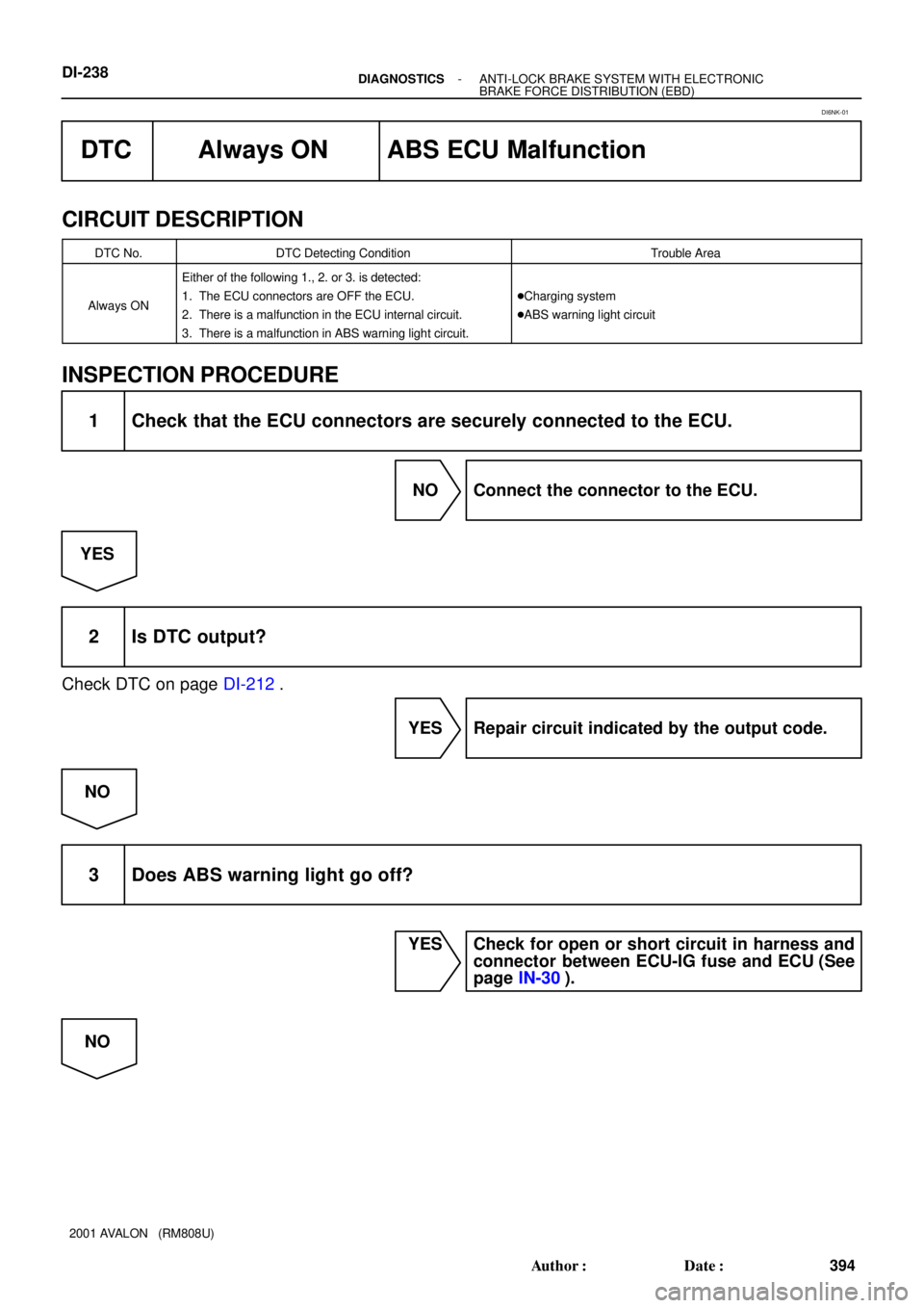
DTC Always ON ABS ECU Malfunction
CIRCUIT DESCRIPTION
DTC No.DTC Detecting ConditionTrouble Area
Always ON
Either of the following 1., 2. or 3. is detected:
1. The ECU connectors are OFF the ECU.
2. There is a malfunction in the ECU internal circuit.
3. There is a malfunction in ABS warning light circuit.
�Charging system
�ABS warning light circuit
INSPECTION PROCEDURE
1 Check that the ECU connectors are securely connected to the ECU.
NO Connect the connector to the ECU.
YES
2 Is DTC output?
Check DTC on page DI-212.
YES Repair circuit indicated by the output code.
NO
3 Does ABS warning light go off?
YES Check for open or short circuit in harness and
connector between ECU-IG fuse and ECU (See
page IN-30).
NO
DI6NK-01