Page 1315 of 1897
P00601
A05416
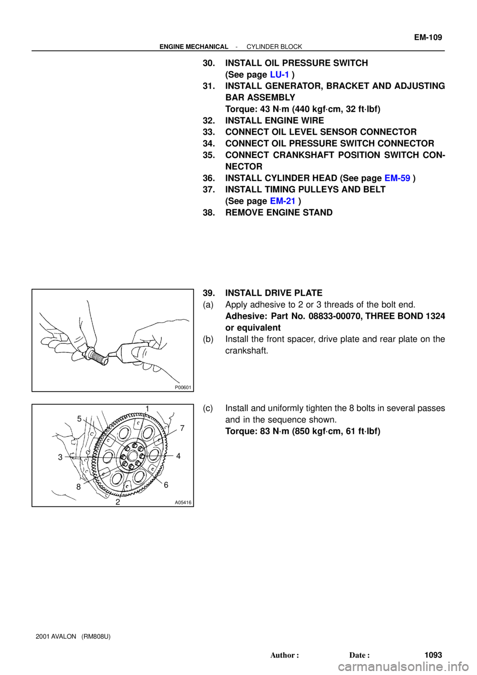
1
2 34 5
67
8
- ENGINE MECHANICALCYLINDER BLOCK
EM-109
1093 Author�: Date�:
2001 AVALON (RM808U)
30. INSTALL OIL PRESSURE SWITCH
(See page LU-1)
31. INSTALL GENERATOR, BRACKET AND ADJUSTING
BAR ASSEMBLY
Torque: 43 N´m (440 kgf´cm, 32 ft´lbf)
32. INSTALL ENGINE WIRE
33. CONNECT OIL LEVEL SENSOR CONNECTOR
34. CONNECT OIL PRESSURE SWITCH CONNECTOR
35. CONNECT CRANKSHAFT POSITION SWITCH CON-
NECTOR
36. INSTALL CYLINDER HEAD (See page EM-59)
37. INSTALL TIMING PULLEYS AND BELT
(See page EM-21)
38. REMOVE ENGINE STAND
39. INSTALL DRIVE PLATE
(a) Apply adhesive to 2 or 3 threads of the bolt end.
Adhesive: Part No. 08833-00070, THREE BOND 1324
or equivalent
(b) Install the front spacer, drive plate and rear plate on the
crankshaft.
(c) Install and uniformly tighten the 8 bolts in several passes
and in the sequence shown.
Torque: 83 N´m (850 kgf´cm, 61 ft´lbf)
Page 1318 of 1897
EM042-03
A10835
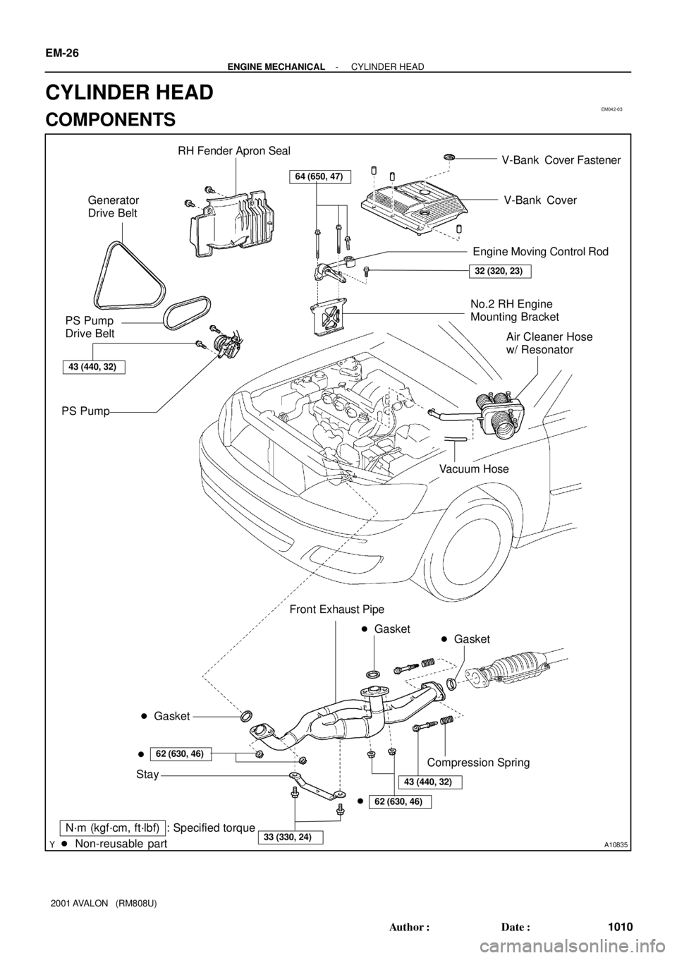
RH Fender Apron Seal
Generator
Drive Belt
No.2 RH Engine
Mounting Bracket
PS Pump
Drive Belt
PS Pump
� Non-reusable part: Specified torque
64 (650, 47)
32 (320, 23)
43 (440, 32)
N´m (kgf´cm, ft´lbf)
� Gasket
62 (630, 46)
43 (440, 32)
� Gasket
�
62 (630, 46)
33 (330, 24)
�Front Exhaust Pipe
Stay
� Gasket
Compression Spring
V-Bank Cover
Air Cleaner Hose
w/ Resonator
Vacuum Hose
Engine Moving Control Rod V-Bank Cover Fastener
EM-26
- ENGINE MECHANICALCYLINDER HEAD
1010 Author�: Date�:
2001 AVALON (RM808U)
CYLINDER HEAD
COMPONENTS
Page 1342 of 1897

11. INSTALL RH EXHAUST MANIFOL")
A06661
Manifold
Stay
A07283
New O-Ring
A07281
Manifold
Stay
A05188Inlet PipeRear
Plate
EM-66
- ENGINE MECHANICALCYLINDER HEAD
1050 Author�: Date�:
2001 AVALON (RM808U)
11. INSTALL RH EXHAUST MANIFOLD
(a) Install a new gasket and the exhaust manifold with the 6
nuts. Uniformly tighten the nuts in several passes.
Torque: 49 N´m (500 kgf´cm, 36 ft´lbf)
(b) Install the exhaust manifold stay with the bolt and nut. Al-
ternately tighten the bolt and nut.
Torque: 34 N´m (350 kgf´cm, 25 ft´lbf)
(c) Connect the A/F sensor connector.
12. INSTALL OIL DIPSTICK AND GUIDE
(a) Install a new O-ring to the dipstick guide.
(b) Apply soapy water to the O-ring.
(c) Push in the dipstick guide end into the guide hole of the
No.1 oil pan.
(d) Install the dipstick guide with the bolt.
Torque: 8 N´m (80 kgf´cm, 69 in.´lbf)
(e) Install the dipstick.
13. INSTALL LH EXHAUST MANIFOLD
(a) Install a new gasket and the exhaust manifold with the 6
nuts. Uniformly tighten the nuts in several passes.
Torque: 49 N´m (500 kgf´cm, 36 ft´lbf)
(b) Install the exhaust manifold stay with the bolt and nut. Al-
ternately tighten the bolt and nut.
Torque: 34 N´m (350 kgf´cm, 25 ft´lbf)
(c) Connect the A/F sensor connector.
14. INSTALL WATER INLET PIPE
(a) Install a new O-ring to the water inlet pipe.
(b) Apply soapy water to the O-ring.
(c) Connect the water inlet pipe to the water inlet.
(d) Install the bolt holding the water inlet pipe to the cylinder
head.
Torque: 19.5 N´m (200 kgf´cm, 14 ft´lbf)
15. INSTALL CYLINDER HEAD REAR PLATE
Torque: 8 N´m (80 kgf´cm, 69 in.´lbf)
16. INSTALL ENGINE WIRE PROTECTOR
17. INSTALL CAMSHAFT TIMING OIL CONTROL VALVES
18. INSTALL CAMSHAFT POSITION SENSORS
19. INSTALL NO.3 TIMING BELT COVER
(a) Check that the timing belt cover gaskets have no cracks
or peeling, etc.
If the gaskets have cracks or peeling etc., replace them using
these steps:
�Using a screwdriver and gasket scraper, remove all
the old gasket material.
Page 1345 of 1897

(n) Install the PS pressure tube with the 2 nuts.
(o) Connect the throttle position sensor connector.
(p) Connect the")
- ENGINE MECHANICALCYLINDER HEAD
EM-69
1053 Author�: Date�:
2001 AVALON (RM808U)
(n) Install the PS pressure tube with the 2 nuts.
(o) Connect the throttle position sensor connector.
(p) Connect the IAC valve connector.
(q) Connect the No.1 VSV connector for the ACIS.
(r) Connect the No.2 VSV connector for the ACIS.
(s) Connect the VSV connecter for the EVAP.
(t) Connect the DLC1 to the bracket on the intake air control
valve.
(u) Connect the throttle cable.
(v) Connect the accelerator cable.
29. INSTALL AIR CLEANER CAP HOSE WITH RESONA-
TOR
30. INSTALL V-BANK COVER
(a) Using a 5 mm hexagon wrench, install the V-bank cover
with the 3 cap nuts.
(b) Press down the V-bank cover fastener.
31. INSTALL FRONT EXHAUST PIPE (See page EM-77)
32. INSTALL PS PUMP (See page SR-35)
33. INSTALL GENERATOR DRIVE BELT
(See page CH-16)
34. FILL WITH ENGINE COOLANT
35. START ENGINE AND CHECK FOR LEAKS
36. VEHICLE ROAD TEST
Check for abnormal noise, shock, slippage, correct shift points
and smoothly operation.
37. RECHECK ENGINE COOLANT LEVEL
Page 1349 of 1897

(k) (l)
- ENGINE MECHANICALCYLINDER HEAD
EM-31
1015 Author�: Date�:
2001 AVALON (RM808U)
REMOVAL
NOTICE:
Do not remove or install the camshaft timing g")
EM0ZE-02
A10518
5 mm
Hexagon
Wrench
A06658
(j)
(k) (l)
- ENGINE MECHANICALCYLINDER HEAD
EM-31
1015 Author�: Date�:
2001 AVALON (RM808U)
REMOVAL
NOTICE:
Do not remove or install the camshaft timing gear (VVT-i)
beside changing VVT-i or the camshaft.
1. DRAIN ENGINE COOLANT
2. REMOVE RH FENDER APRON SEAL
3. REMOVE GENERATOR DRIVE BELT
(See page CH-6)
4. REMOVE PS PUMP (See page SR-27)
5. REMOVE FRONT EXHAUST PIPE (See page EM-72)
6. REMOVE V-BANK COVER
(a) Using a 5 mm hexagon wrench, remove the 3 cap nuts.
(b) Loosen the V-bank cover fastener counterclockwise.
(c) Remove the V-bank cover.
7. REMOVE AIR CLEANER HOSE WITH RESONATOR
8. REMOVE AIR INTAKE CHAMBER ASSEMBLY
(a) Disconnect the accelerator cable.
(b) Disconnect the throttle cable.
(c) Disconnect the throttle position sensor connector.
(d) Disconnect the IAC valve connector.
(e) Disconnect the No.1 VSV connector for the ACIS.
(f) Disconnect the No.2 VSV connector for the ACIS.
(g) Disconnect the VSV connector for the EVAP.
(h) Disconnect the DLC1 from the bracket on the intake air
control valve.
(i) Remove the 2 nuts, and disconnect the PS pressure tube
from the No.1 engine hanger.
(j) Disconnect the PCV hose from the PCV valve on the RH
cylinder head.
(k) Disconnect the ground strap and cable from the intake air
control valve for the ACIS.
(l) Disconnect the ground cable from the air intake chamber.
Page 1362 of 1897

EM0ZK-02
A10837
No.2 Cooling Fan Connector
Upper Radiator
Support
Radiator
Assembly RH Fender
Apron
Seal
Generator
Drive
Belt
A/C Compressor
Connector
Battery
Insulator
Battery
Battery
Tray Generator Drive
Belt Adjusting
Bar Bracket
LH Fender
Apron Seal
� Gasket A/C Compressor
43 (440, 32)
25 (250, 18)
�Non-reusable partStay
N´m (kgf´cm, ft´lbf) Front Exhaust Pipe: Specified torque� Gasket
62 (630, 46)
33 (330, 24)
�
62 (630, 46)
43 (430, 32)
� Gasket
Actuator Cover No.3 Engine Room
Relay BlockHood
Hold-Down
Clamp
Washer
Hose for
Windshield
Air Filter
Air Cleaner Case � O-Ring
Drain Plug Lower Radiator
SupportAir Cleaner
Cap Assembly Radiator Upper Hose
Cruise Control
Actuator
Cruise Control
Actuator
ConnectorAccelerator Cable
PS Pump
� PS Pump
Drive Belt
Compression Spring
V-Bank Cover
A/T Oil Cooler Hose
Radiator Lower
HoseEVAP Hose
Assembly
MAF Meter Connector
VSV for Active
Control Engine
Mount
No.1 ECT Switch Wire Connector
No.1 Cooling Fan Connector
Vacuum Hose
Air Hose
EM-70
- ENGINE MECHANICALENGINE UNIT
1054 Author�: Date�:
2001 AVALON (RM808U)
ENGINE UNIT
COMPONENTS
Page 1366 of 1897

7. INSTALL ENGINE MOUNTING ABSORBER
Install the engine mounting a")
A07431
P18752
A07430
P18775
A10833
BracketA
B
A
A
C
A EM-78
- ENGINE MECHANICALENGINE UNIT
1062 Author�: Date�:
2001 AVALON (RM808U)
7. INSTALL ENGINE MOUNTING ABSORBER
Install the engine mounting absorber with the 4 bolts.
Torque: 48 N´m (490 kgf´cm, 35 ft´lbf)
8. CONNECT REAR ENGINE MOUNTING INSULATOR
(a) Connect the mounting insulator with the 4 nuts.
Torque: 66 N´m (670 kgf´cm, 48 ft´lbf)
(b) Install the 2 hole plugs.
9. CONNECT LH ENGINE MOUNTING INSULATOR
Connect the mounting insulator with the 4 bolts.
Torque: 64 N´m (650 kgf´cm, 47 ft´lbf)
10. REMOVE ENGINE SLING DEVICE
11. CONNECT TRANSAXLE CONTROL CABLE TO
TRANSAXLE
12. INSTALL PS PUMP
(a) Install the PS pump with the 2 bolts.
Torque: 43 N´m (440 kgf´cm, 31 ft´lbf)
(b) Install the drive belt.
(c) Connect the PS pressure tube with the 2 nuts.
13. INSTALL A/C COMPRESSOR
(a) Install the A/C compressor and drive belt adjusting bar
bracket with the 5 bolts and nut.
Torque:
25 N´m (250 kgf´cm, 18 ft´lbf) for bolt A
18 N´m (185 kgf´cm, 13 ft´lbf) for bolt B
25 N´m (250 kgf´cm, 18 ft´lbf) for nut C
(b) Install the drive belt.
(c) Connect the A/C compressor connector.
14. INSTALL DRIVE SHAFTS (See page SA-24)
Page 1370 of 1897

(j) Disconnect the fuel inlet hose from the fuel filter.
CAUTION:
Perform disconne")
S04497
A10833
Bracket
P18775
A07430
- ENGINE MECHANICALENGINE UNIT
EM-73
1057 Author�: Date�:
2001 AVALON (RM808U)
(j) Disconnect the fuel inlet hose from the fuel filter.
CAUTION:
Perform disconnecting operation of the fuel tube connec-
tor (quick type) after observing the precautions (See page
SF-1).
(k) Disconnect the EVAP hose assembly from the pipe on the
emission control valve set.
(l) Disconnect the 2 vacuum hoses from the vacuum tank for
the ACIS.
13. DISCONNECT ENGINE WIRE FROM CABIN
(a) Remove the glove compartment.
(b) Disconnect the 5 ECM connectors.
(c) Disconnect the grommet from the cowl panel, and pull out
the engine wire.
14. REMOVE DRIVE SHAFTS (See page SA-16)
15. DISCONNECT A/C COMPRESSOR FROM ENGINE
(a) Disconnect the A/C compressor connector.
(b) Remove the drive belt.
(c) Remove the 5 bolts, nut and drive belt adjusting bar
bracket.
(d) Disconnect the A/C compressor from the engine.
16. DISCONNECT TRANSAXLE CONTROL CABLE FROM
TRANSAXLE
17. DISCONNECT PS PUMP FROM ENGINE
(a) Remove the 2 nuts, and disconnect the PS pressure tube
from the No.1 engine hanger.
(b) Loosen the 2 bolts, and remove the drive belt.
(c) Remove the 2 bolts, and disconnect the PS pump from
the engine.
18. DISCONNECT TRANSAXLE FROM LH ENGINE
MOUNTING INSULATOR
Remove the 4 bolts holding the transaxle to the mounting insu-
lator.