Page 347 of 1897

BO2OO-01
H12112
Rear Lower FrameDoor Lock Striker23 (230, 17)
Front Door Weatherstrip
Door Glass Run
Outside Rear View
Mirror
Door Glass
Lower Frame
Bracket Garnish
7.8 (80, 69 in.´lbf)25 (260, 19)
5.4 (55, 48 in.´lbf)
Outside Handle
Key Cylinder
5.4 (55, 48 in.´lbf)
Door
Hinge
7.8 (80, 69 in.´lbf)
Door Check
25 (260, 19)
Door Speaker BoardFront Lower
Frame
25 (260, 19)
Door Hinge
Front Door Outside Lower Moulding
Door Lock Protector
Service Hole Cover
5.4 (55, 48 in.´lbf)
� Precoated part
Door LockInside Handle
4.9 (50, 43 in.´lbf)
Inside Handle
Bezel
Cover
Door TrimUpper Armrest
Base Panel
Power Window Switch
Front Door Armrest
Courtesy Light
Front Door
Belt Moulding Front Door
Inner Weatherstrip
x10
5.4 (55, 48 in.´lbf)
Window Regulator
Guide Assembly
5.4 (55, 48 in.´lbf)
x8
x4
Window Regulator Motor
No. 2 Service Hole Cover
Front Door Trim Pocket : Specified torqueN´m (kgf´cm, ft´lbf)
BO-8
- BODYFRONT DOOR
1793 Author�: Date�:
2001 AVALON (RM808U)
FRONT DOOR
COMPONENTS
Page 349 of 1897

H12104Clip
H06127
H12105
H12106
BO-10
- BODYFRONT DOOR
1795 Author�: Date�:
2001 AVALON (RM808U)
5. REMOVE LOWER FRAME BRACKET GARNISH
Using a screwdriver, remove the lower frame bracket as shown
in the illustration.
HINT:
Tape the screwdriver tip before use.
6. REMOVE OUTSIDE REAR VIEW MIRROR
Torque: 7.8 N´m (80 kgf´cm, 69 ft´lbf)
7. REMOVE DOOR SPEAKER BOARD
8. REMOVE INSIDE HANDLE
(a) Remove the screw.
(b) Slide the inside handle backward to remove it.
(c) Disconnect the 2 cables from the inside handle as shown
in the illustration.
9. REMOVE SERVICE HOLE COVER
(a) Using a clip remover, remove the grommets.
(b) Remove the service hole cover.
NOTICE:
Do not tear the cover.
HINT:
At the time of reassembly, please refer to the following item.
Bring out the 2 control cables and wire harness through the ser-
vice hole cover.
10. REMOVE FRONT DOOR WEATHERSTRIP
(a) Using a clip remover, remove the clip.
(b) Remove the screw from the door check.
(c) Using a clip remover, remove the front door weatherstrip.
(d) Reinstall the screw to the door check.
Torque: 25 N´m (260 kgf´cm, 19 ft´lbf)
Page 377 of 1897

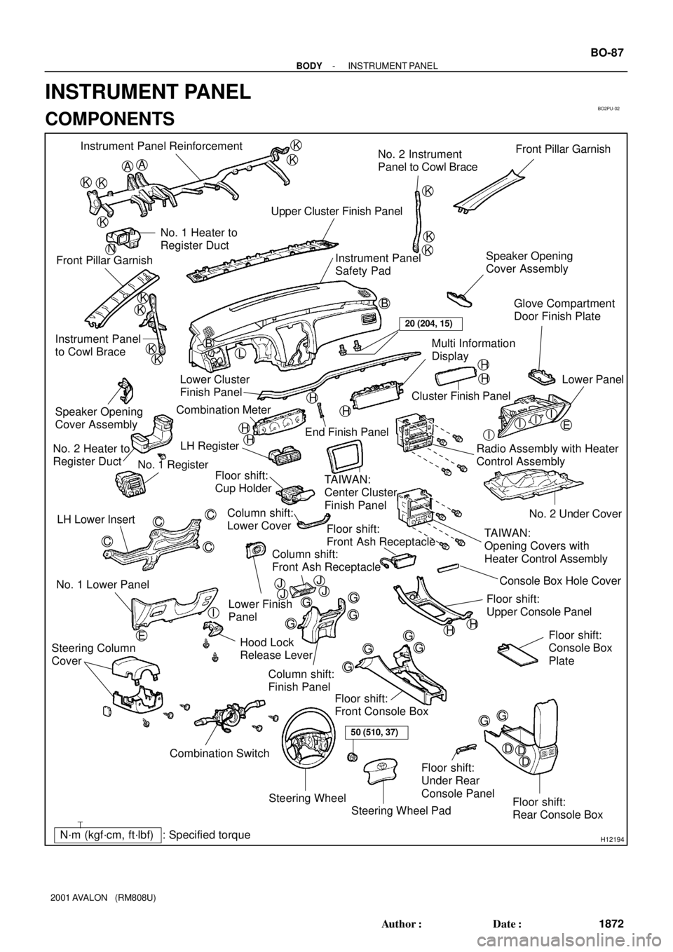
BO2PU-02
H12194: Specified torqueN´m (kgf´cm, ft´lbf)
AA
KK
K
K
K
K
K
K
B
L
E
G
GG
G
GG
G
GGI
C
C
C
C
K
K
KKB Instrument Panel Reinforcement
No. 2 Instrument
Panel to Cowl BraceFront Pillar Garnish
Upper Cluster Finish Panel
Instrument Panel
Safety Pad Front Pillar GarnishNo. 1 Heater to
Register Duct
Instrument Panel
to Cowl BraceSpeaker Opening
Cover Assembly
H
H
H
H
H
H
III
G
D EDD
Steering Wheel
Floor shift:
Rear Console Box Floor shift:
Front Console Box
Combination Switch No. 1 Lower PanelLH Lower Insert
Column shift:
Finish Panel Hood Lock
Release LeverNo. 2 Under Cover
Floor shift:
Console Box
Plate
Steering Wheel Pad Steering Column
Cover
Floor shift:
Front Ash Receptacle
Floor shift:
Upper Console PanelLower Finish
Panel Column shift:
Lower Cover LH Register
TAIWAN:
Center Cluster
Finish Panel
TAIWAN:
Opening Covers with
Heater Control Assembly Radio Assembly with Heater
Control AssemblyLower Panel
Cluster Finish Panel
End Finish Panel Combination Meter Lower Cluster
Finish PanelGlove Compartment
Door Finish Plate
Speaker Opening
Cover Assembly
No. 2 Heater to
Register Duct
No. 1 Register
Floor shift:
Cup Holder
Multi Information
Display
Floor shift:
Under Rear
Console Panel
I
HH
50 (510, 37)
20 (204, 15)
N
JJJJConsole Box Hole Cover
Column shift:
Front Ash Receptacle
- BODYINSTRUMENT PANEL
BO-87
1872 Author�: Date�:
2001 AVALON (RM808U)
INSTRUMENT PANEL
COMPONENTS
Page 386 of 1897

H12186
2 Clips
H12187
4 Clips
H12188
2 Clips
H12189
- BODYINSTRUMENT PANEL
BO-93
1878 Author�: Date�:
2001 AVALON (RM808U)
24. Column shift:
REMOVE LOWER COVER
Using a screwdriver, remove the lower cover.
HINT:
Tape the screwdriver tip before use.
25. Column shift:
REMOVE FINISH PANEL
(a) Remove the 4 screws and 2 clips.
(b) Using a screwdriver, remove the finish panel, then discon-
nect the connector.
HINT:
Tape the screwdriver tip before use.
(c) Remove the 4 screws and front ash receptacle.
26. Column shift:
REMOVE RADIO ASSEMBLY WITH HEATER CON-
TROL ASSEMBLY
Remove the 4 bolts and radio assembly with heater control as-
sembly.
27. REMOVE SPEAKER OPENING COVER ASSEMBLY
(a) Using a screwdriver, remove the speaker opening cover
assembly, then disconnect the connector.
HINT:
Tape the screwdriver tip before use.
(b) Employ the same manner described above to the other
side.
28. REMOVE UPPER CLUSTER FINISH PANEL
Using a screwdriver, remove the upper cluster finish panel.
HINT:
Tape the screwdriver tip before use.
Page 388 of 1897

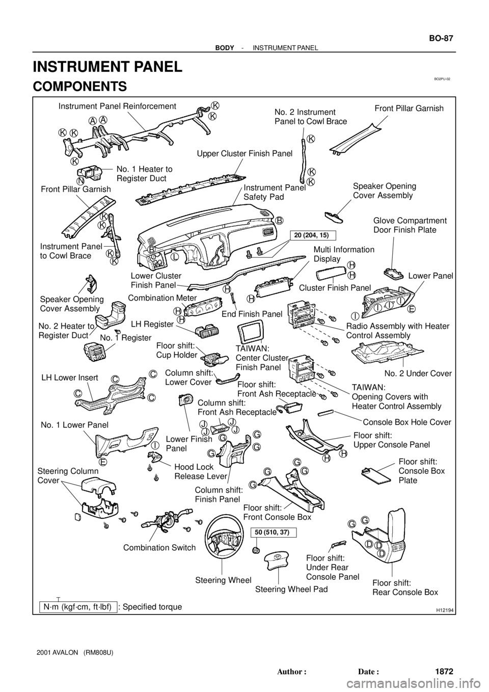
BO2PU-02
H12194: Specified torqueN´m (kgf´cm, ft´lbf)
AA
KK
K
K
K
K
K
K
B
L
E
G
GG
G
GG
G
GGI
C
C
C
C
K
K
KKB Instrument Panel Reinforcement
No. 2 Instrument
Panel to Cowl BraceFront Pillar Garnish
Upper Cluster Finish Panel
Instrument Panel
Safety Pad Front Pillar GarnishNo. 1 Heater to
Register Duct
Instrument Panel
to Cowl BraceSpeaker Opening
Cover Assembly
H
H
H
H
H
H
III
G
D EDD
Steering Wheel
Floor shift:
Rear Console Box Floor shift:
Front Console Box
Combination Switch No. 1 Lower PanelLH Lower Insert
Column shift:
Finish Panel Hood Lock
Release LeverNo. 2 Under Cover
Floor shift:
Console Box
Plate
Steering Wheel Pad Steering Column
Cover
Floor shift:
Front Ash Receptacle
Floor shift:
Upper Console PanelLower Finish
Panel Column shift:
Lower Cover LH Register
TAIWAN:
Center Cluster
Finish Panel
TAIWAN:
Opening Covers with
Heater Control Assembly Radio Assembly with Heater
Control AssemblyLower Panel
Cluster Finish Panel
End Finish Panel Combination Meter Lower Cluster
Finish PanelGlove Compartment
Door Finish Plate
Speaker Opening
Cover Assembly
No. 2 Heater to
Register Duct
No. 1 Register
Floor shift:
Cup Holder
Multi Information
Display
Floor shift:
Under Rear
Console Panel
I
HH
50 (510, 37)
20 (204, 15)
N
JJJJConsole Box Hole Cover
Column shift:
Front Ash Receptacle
- BODYINSTRUMENT PANEL
BO-87
1872 Author�: Date�:
2001 AVALON (RM808U)
INSTRUMENT PANEL
COMPONENTS
Page 397 of 1897

H12186
2 Clips
H12187
4 Clips
H12188
2 Clips
H12189
- BODYINSTRUMENT PANEL
BO-93
1878 Author�: Date�:
2001 AVALON (RM808U)
24. Column shift:
REMOVE LOWER COVER
Using a screwdriver, remove the lower cover.
HINT:
Tape the screwdriver tip before use.
25. Column shift:
REMOVE FINISH PANEL
(a) Remove the 4 screws and 2 clips.
(b) Using a screwdriver, remove the finish panel, then discon-
nect the connector.
HINT:
Tape the screwdriver tip before use.
(c) Remove the 4 screws and front ash receptacle.
26. Column shift:
REMOVE RADIO ASSEMBLY WITH HEATER CON-
TROL ASSEMBLY
Remove the 4 bolts and radio assembly with heater control as-
sembly.
27. REMOVE SPEAKER OPENING COVER ASSEMBLY
(a) Using a screwdriver, remove the speaker opening cover
assembly, then disconnect the connector.
HINT:
Tape the screwdriver tip before use.
(b) Employ the same manner described above to the other
side.
28. REMOVE UPPER CLUSTER FINISH PANEL
Using a screwdriver, remove the upper cluster finish panel.
HINT:
Tape the screwdriver tip before use.
Page 400 of 1897

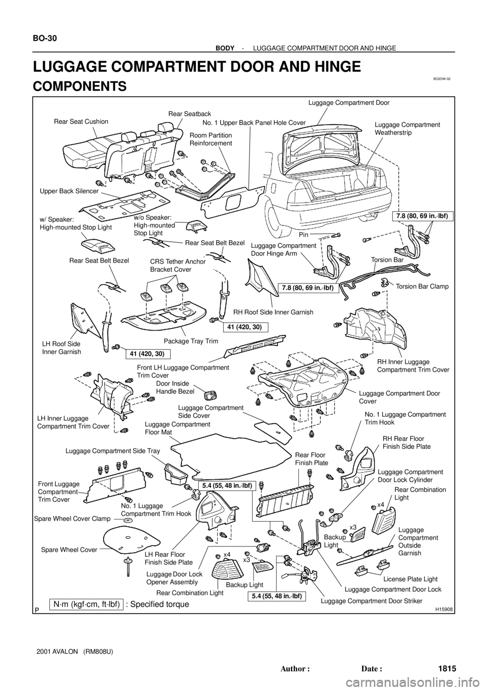
BO2OW-02
H15908
Rear SeatbackRear Seat Cushion
Upper Back Silencer
w/ Speaker:
High-mounted Stop Light
Luggage Compartment Door
Luggage Compartment
Weatherstrip
Luggage Compartment
Door Hinge Arm
w/o Speaker:
High-mounted
Stop Light
Rear Seat Belt Bezel
Rear Seat Belt Bezel
LH Roof Side
Inner Garnish
CRS Tether Anchor
Bracket Cover
Package Tray Trim
RH Roof Side Inner GarnishPin
Torsion Bar
Torsion Bar Clamp
RH Inner Luggage
Compartment Trim CoverFront LH Luggage Compartment
Trim Cover
LH Inner Luggage
Compartment Trim Cover
Front Luggage
Compartment
Trim Cover
Luggage Compartment Side Tray
Luggage Compartment
Floor Mat
Luggage Compartment
Side Cover
Luggage Compartment Door
Cover
No. 1 Luggage Compartment
Trim Hook
RH Rear Floor
Finish Side Plate
Rear Floor
Finish Plate
No. 1 Luggage
Compartment Trim Hook
Spare Wheel Cover Clamp
Luggage Compartment
Door Lock Cylinder
Rear Combination
Light
Spare Wheel CoverLH Rear Floor
Finish Side Platex4
x3
Backup Light
Rear Combination Light
Luggage Compartment Door Striker
Backup
Light
x3x4
Luggage Compartment Door LockLicense Plate Light
N´m (kgf´cm, ft´lbf) : Specified torque
7.8 (80, 69 in.´lbf)
7.8 (80, 69 in.´lbf)
Luggage
Compartment
Outside
Garnish
41 (420, 30)
41 (420, 30)
No. 1 Upper Back Panel Hole Cover
Room Partition
Reinforcement
Door Inside
Handle Bezel
5.4 (55, 48 in.´lbf)
Luggage Door Lock
Opener Assembly
5.4 (55, 48 in.´lbf)
BO-30
- BODYLUGGAGE COMPARTMENT DOOR AND HINGE
1815 Author�: Date�:
2001 AVALON (RM808U)
LUGGAGE COMPARTMENT DOOR AND HINGE
COMPONENTS
Page 405 of 1897
H12128
:7 Clips
H03125H12122H12806
w/o Speaker:
w/ Speaker:
2 Clips
H07599
H12124
2 Clips BO-32
- BODYLUGGAGE COMPARTMENT DOOR AND HINGE
1817 Author�: Date�:
2001 AVALON (RM808U)
17. REMOVE ROOF SIDE INNER GARNISH
(a) Using a screwdriver, remove the roof side inner garnish.
HINT:
Tape the screwdriver tip before use.
(b) Employ the same manner described above to the other
side.
18. REMOVE HIGH-MOUNTED STOP LIGHT
Remove the high-mounted stop light as shown in the illustra-
tion, then disconnect the connector.
19. REMOVE PACKAGE TRAY TRIM
(a) Using a screwdriver, remove the 3 rear seat belt bezel.
HINT:
Tape the screwdriver tip before use.
(b) Remove the package tray trim as shown in the illustration.
20. REMOVE UPPER BACK SILENCER
21. REMOVE TORSION BAR
(a) Disconnect the torsion bars from the torsion bar clamp,
then remove the torsion bar clamp.