Page 569 of 1897

REPLACEMENT
1. DRAIN ENGINE COOLANT
(a) Remove the radiator cap from the water outlet.
CAUTION:
To")
CO02L-03
B09030Drain PlugDrain Plug
CO-2
- COOLINGCOOLANT
1195 Author�: Date�:
2001 AVALON (RM808U)
REPLACEMENT
1. DRAIN ENGINE COOLANT
(a) Remove the radiator cap from the water outlet.
CAUTION:
To avoid the danger of being burned, do not remove the ra-
diator cap while the engine and radiator are still hot, as fluid
and steam can be blown out under pressure.
(b) Loosen the radiator drain plug and engine drain plugs,
and drain the coolant.
(c) Close the drain plugs.
Torque:
RH engine drain plug on cylinder block side cover:
7 N´m (70 kgf´cm, 61 in.´lbf)
LH engine drain plug on union:
13 N´m (130 kgf´cm, 9 ft´lbf)
2. FILL ENGINE COOLANT
(a) Slowly fill the system with coolant.
�Use of improper coolants may damage engine cool-
ing system.
�Use ºToyota Long life Coolantº or equivalent and
mix it with plan water according to the manufactur-
er's directions.
�Using of coolant which includes more than 50 %
(freezing protection down to -35°C (-31°F) or 60 %
(freezing protection down to -50°C (-58°F)) of eth-
ylene-glycol is recommended but not more than 70
%.
NOTICE:
�Do not use an alcohol type coolant or plain water
alone.
�The coolant should be mixed with plain water (prefer-
ably demineralized water or distilled water).
Capacity: 9.0 liters (9.5 US qts, 7.9 lmp. qts)
(b) Install the radiator cap.
(c) Start the engine, and bleed the cooling system.
(d) If necessary, refill coolant into the reservoir up to the
ºFULLº line.
3. CHECK ENGINE COOLANT FOR LEAKS
4. CHECK ENGINE COOLANT SPECIFIC GRAVITY COR-
RECTLY
Page 571 of 1897
B09037
No.2
Fan
NutFan Shroud
Fan Motor
No.2 Cooling Fan Connector
No.2 Cooling Fan
Upper Radiator Hose
� Non-reusable part
No.1 ECT Switch Wire Connector
No.1 ECT Switch Wire
CO-26
- COOLINGELECTRIC COOLING FAN
1219 Author�: Date�:
2001 AVALON (RM808U)
Page 575 of 1897
CO09O-02
B09051
No.1
B09052
No.2
- COOLINGELECTRIC COOLING FAN
CO-27
1220 Author�: Date�:
2001 AVALON (RM808U)
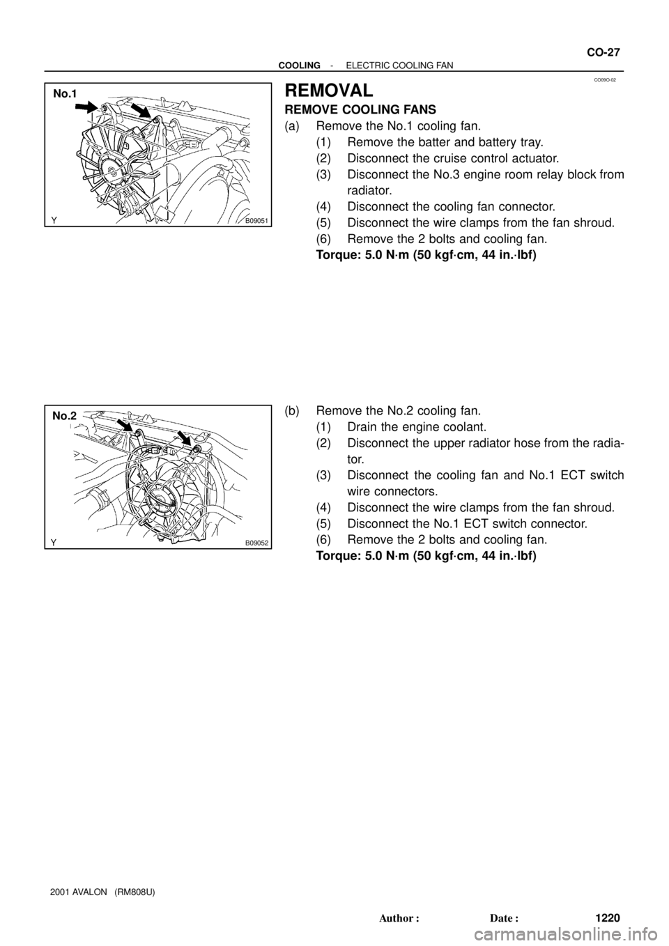
REMOVAL
REMOVE COOLING FANS
(a) Remove the No.1 cooling fan.
(1) Remove the batter and battery tray.
(2) Disconnect the cruise control actuator.
(3) Disconnect the No.3 engine room relay block from
radiator.
(4) Disconnect the cooling fan connector.
(5) Disconnect the wire clamps from the fan shroud.
(6) Remove the 2 bolts and cooling fan.
Torque: 5.0 N´m (50 kgf´cm, 44 in.´lbf)
(b) Remove the No.2 cooling fan.
(1) Drain the engine coolant.
(2) Disconnect the upper radiator hose from the radia-
tor.
(3) Disconnect the cooling fan and No.1 ECT switch
wire connectors.
(4) Disconnect the wire clamps from the fan shroud.
(5) Disconnect the No.1 ECT switch connector.
(6) Remove the 2 bolts and cooling fan.
Torque: 5.0 N´m (50 kgf´cm, 44 in.´lbf)
Page 578 of 1897
CO02W-03
B09039
Radiator
No.1 ECT Switch
No.2 Cooling Fan Connector
Upper Radiator
Support
Upper Radiator
HoseNo.1 Cooling Fan Connector
No.1 ECT Switch Wire Connector
Radiator Assembly
Lower Radiator
Support� O-Ring
A/T Oil Cooler Hose
No.3 Engine
Room Relay Block No.1 Cooling Fan
� Non-reusable part � O-Ring
Drain Plug
Lower Radiator
Hose
No.2 Cooling Fan
Battery
Insulator
Battery
Battery
Tray Hold-Down
Clamp
Engine Under Cover
- COOLINGRADIATOR
CO-15
1208 Author�: Date�:
2001 AVALON (RM808U)
COMPONENTS
Page 579 of 1897
B09036
� O-Ring
� Non-reusable partUpper Tank
Cushion
Core
Oil Cooler
Lower TankInlet Pipe
Plate WasherNut
� O-Ring � O-Ring
CO-16
- COOLINGRADIATOR
1209 Author�: Date�:
2001 AVALON (RM808U)
Page 580 of 1897

CO02Y-03
CO1205
Dimension ºBºPart ºAº
Stopper Bolt SST
Claw
Overhaul Handle
B09048
Tank
SST
Lock Plate
Stopper Bolt
B09042
Ta p
B09043
CO-18
- COOLINGRADIATOR
1211 Author�: Date�:
2001 AVALON (RM808U)
DISASSEMBLY
1. REMOVE CUSHION FROM RADIATOR
2. ASSEMBLE SST
SST 09230-01010
(a) Install the claw to the overhaul handle, inserting it in the
hole in part ºAº as shown in the diagram.
(b) While gripping the handle, adjust the stopper bolt so that
dimension ºBº shown in the diagram is 0.2 - 0.5 mm
(0.008 - 0.020 in.).
NOTICE:
If this adjustment is not done, the claw may be damaged.
3. UNCAULK LOCK PLATES
Using SST to release the caulking, squeeze the handle until
stopped by the stopper bolt.
SST 09230-01010
4. REMOVE TANKS AND O-RINGS
(a) Lightly tap the bracket of the radiator (or radiator hose in-
let or outlet) with a soft-faced hammer and remove the
tank.
(b) Remove the O-ring.
5. REMOVE OIL COOLER FROM LOWER TANK
(a) Remove the pipe.
(b) Remove the nuts and plate washers.
(c) Remove the oil cooler and O-rings.
Page 581 of 1897
CO030-01
CO-22
- COOLINGRADIATOR
1215 Author�: Date�:
2001 AVALON (RM808U)
INSTALLATION
Installation is in the reverse order of removal (See page CO-17).
Page 582 of 1897
CO09H-01
- COOLINGRADIATOR
CO-13
1206 Author�: Date�:
2001 AVALON (RM808U)
RADIATOR
ON-VEHICLE CLEANING
Using water or a steam cleaner, remove any mud or dirt from the radiator core.
NOTICE:
If using a high pressure type cleaner, be careful not to deform the fins of the radiator core. (i.e. Main-
tain a distance between the cleaner nozzle and radiator core)