Page 1362 of 1897

EM0ZK-02
A10837
No.2 Cooling Fan Connector
Upper Radiator
Support
Radiator
Assembly RH Fender
Apron
Seal
Generator
Drive
Belt
A/C Compressor
Connector
Battery
Insulator
Battery
Battery
Tray Generator Drive
Belt Adjusting
Bar Bracket
LH Fender
Apron Seal
� Gasket A/C Compressor
43 (440, 32)
25 (250, 18)
�Non-reusable partStay
N´m (kgf´cm, ft´lbf) Front Exhaust Pipe: Specified torque� Gasket
62 (630, 46)
33 (330, 24)
�
62 (630, 46)
43 (430, 32)
� Gasket
Actuator Cover No.3 Engine Room
Relay BlockHood
Hold-Down
Clamp
Washer
Hose for
Windshield
Air Filter
Air Cleaner Case � O-Ring
Drain Plug Lower Radiator
SupportAir Cleaner
Cap Assembly Radiator Upper Hose
Cruise Control
Actuator
Cruise Control
Actuator
ConnectorAccelerator Cable
PS Pump
� PS Pump
Drive Belt
Compression Spring
V-Bank Cover
A/T Oil Cooler Hose
Radiator Lower
HoseEVAP Hose
Assembly
MAF Meter Connector
VSV for Active
Control Engine
Mount
No.1 ECT Switch Wire Connector
No.1 Cooling Fan Connector
Vacuum Hose
Air Hose
EM-70
- ENGINE MECHANICALENGINE UNIT
1054 Author�: Date�:
2001 AVALON (RM808U)
ENGINE UNIT
COMPONENTS
Page 1368 of 1897
EM-80
- ENGINE MECHANICALENGINE UNIT
1064 Author�: Date�:
2001 AVALON (RM808U)
(d) Install the support stay with the 2 bolts.
Torque: 33 N´m (330 kgf´cm, 24 ft´lbf)
18. INSTALL RADIATOR (See page CO-22)
19. INSTALL CRUISE CONTROL ACTUATOR
20. INSTALL AIR CLEANER CAP ASSEMBLY AND AIR
CLEANER CASE
21. CONNECT ACCELERATOR CABLE
22. INSTALL V-BANK COVER
(a) Using a 5 mm hexagon wrench, install the V-bank cover
with the 3 cap nuts.
(b) Press down the V-bank cover fastener.
23. INSTALL ENGINE FENDER APRON SEALS
24. INSTALL BATTERY TRAY AND BATTERY
25. INSTALL HOOD
26. FILL ENGINE WITH OIL
27. FILL WITH ENGINE COOLANT
28. START ENGINE AND CHECK FOR LEAKS
29. PERFORM ROAD TEST
Check for abnormal noise, shock, slippage, correct shift points
and smooth operation.
30. RECHECK ENGINE COOLANT AND OIL LEVELS
Page 1369 of 1897

REMOVAL
1. REMOVE BATTERY AND TRAY
2. REMOVE HOOD
3. REMOVE ENGINE FENDER AP")
EM0ZL-02
A10518
5 mm
Hexagon
Wrench
A07300
EM-72
- ENGINE MECHANICALENGINE UNIT
1056 Author�: Date�:
2001 AVALON (RM808U)
REMOVAL
1. REMOVE BATTERY AND TRAY
2. REMOVE HOOD
3. REMOVE ENGINE FENDER APRON SEALS
4. DRAIN ENGINE COOLANT
5. DRAIN ENGINE OIL
6. REMOVE V-BANK COVER
(a) Using a 5 mm hexagon wrench, remove the 3 cap nuts.
(b) Loosen the V-bank cover fastener counterclockwise.
(c) Remove the V-bank cover.
7. DISCONNECT ACCELERATOR CABLE
8. REMOVE AIR CLEANER CAP ASSEMBLY AND AIR
CLEANER CASE
9. REMOVE CRUISE CONTROL ACTUATOR
10. REMOVE RADIATOR (See page CO-17)
11. REMOVE FRONT EXHAUST PIPE
(a) Remove the 2 bolts holding the support stay to the sup-
port bracket.
(b) Remove the 2 bolts and 2 compression springs holding
the front exhaust pipe to the center exhaust pipe.
(c) Remove the 4 nuts holding the front exhaust pipe to the
exhaust manifolds.
(d) Remove the front exhaust pipe and 3 gaskets.
12. DISCONNECT CONNECTORS, CABLE, CLAMPS AND
HOSES
(a) Remove the bolt and disconnect the ground strap from
the LH fender apron.
(b) Disconnect the 2 ground strap connectors from the RH
fender apron.
(c) Disconnect the ground cable from the A/T.
(d) Disconnect the engine wire protector clamp from the bat-
tery body bracket.
(e) Disconnect the engine wire clamp from the bracket on the
RH fender apron.
(f) Disconnect the brake booster vacuum hose from the
throttle body.
(g) Disconnect the engine coolant reservoir hose from the
water outlet.
(h) Disconnect the heater hose from the intake manifold.
(i) Disconnect the heater hose from the water inlet housing.
Page 1390 of 1897

VALVE CLEARANCE
INSPECTION
HINT:
Inspect and adjust")
EM03V-03
P18805
A05273
RH EX
RH IN
LH IN
LH EX 3 3
11Front
2266 EM-4
- ENGINE MECHANICALVALVE CLEARANCE
988 Author�: Date�:
2001 AVALON (RM808U)
VALVE CLEARANCE
INSPECTION
HINT:
Inspect and adjust the valve clearance when the engine is cold.
1. REMOVE RH FENDER APRON SEAL
2. DRAIN ENGINE COOLANT
3. REMOVE V-BANK COVER
(a) Using a 5 mm hexagon wrench, remove the 3 cap nuts.
(b) Loosen the V-bank cover fastener counterclockwise.
(c) Remove the V-bank cover.
4. REMOVE AIR INTAKE CHAMBER ASSEMBLY (See
page EM-31)
5. REMOVE IGNITION COILS
6. DISCONNECT UPPER RADIATOR HOSE FROM WA-
TER OUTLET
7. REMOVE CYLINDER HEAD COVERS
(See page EM-31)
8. SET NO.1 CYLINDER TO TDC/COMPRESSION
(a) Turn the crankshaft pulley, and align its groove with the
timing mark º0º of the No.1 timing belt cover.
(b) Check that the valve lifters on the No.1 (IN and EX) are
loose.
If not, turn the crankshaft 1 revolution (360°) and align the mark
as above.
9. INSPECT VALVE CLEARANCE
(a) Check only those valves indicated in the illustration.
(1) Using a feeler gauge, measure the clearance be-
tween the valve lifter and camshaft.
(2) Record out of specification valve clearance mea-
surements. They will be used later to determine the
required replacement adjusting shim.
Valve clearance (Cold):
Intake0.15 - 0.25 mm (0.006 - 0.010 in.)
Exhaust0.25 - 0.35 mm (0.010 - 0.014 in.)
Page 1393 of 1897
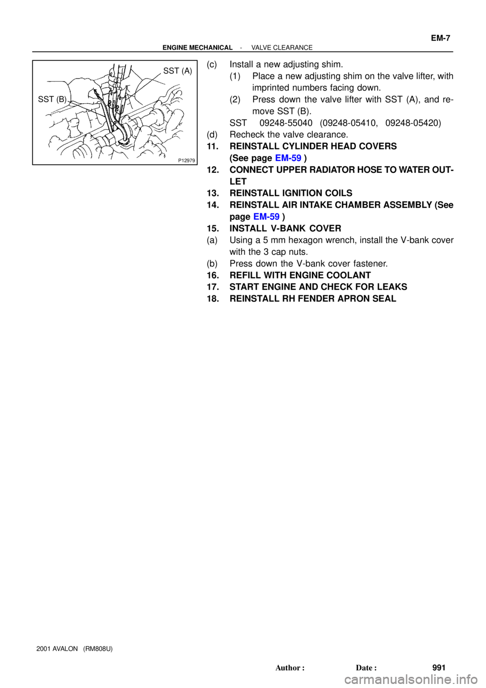
P12979
SST (A)
SST (B)
- ENGINE MECHANICALVALVE CLEARANCE
EM-7
991 Author�: Date�:
2001 AVALON (RM808U)
(c) Install a new adjusting shim.
(1) Place a new adjusting shim on the valve lifter, with
imprinted numbers facing down.
(2) Press down the valve lifter with SST (A), and re-
move SST (B).
SST 09248-55040 (09248-05410, 09248-05420)
(d) Recheck the valve clearance.
11. REINSTALL CYLINDER HEAD COVERS
(See page EM-59)
12. CONNECT UPPER RADIATOR HOSE TO WATER OUT-
LET
13. REINSTALL IGNITION COILS
14. REINSTALL AIR INTAKE CHAMBER ASSEMBLY (See
page EM-59)
15. INSTALL V-BANK COVER
(a) Using a 5 mm hexagon wrench, install the V-bank cover
with the 3 cap nuts.
(b) Press down the V-bank cover fastener.
16. REFILL WITH ENGINE COOLANT
17. START ENGINE AND CHECK FOR LEAKS
18. REINSTALL RH FENDER APRON SEAL
Page 1421 of 1897

(2)
4 OTHER: When a malfunction seems to occur when electrical load")
B02389
B02390
HEAT METHOD: When the problem seems to occur when the suspect area is heated. 2
NOTICE:3 WATER SPRINKLING METHOD:
(1)
(2)
4 OTHER: When a malfunction seems to occur when electrical load is excessive.When the malfunction seems to occur on a rainy day or in a
high-humidity condition. Heat the component that is the likely cause of the malfunction
with a hair dryer or similar object. Check to see if the malfunction
occurs.
Sprinkle water onto the vehicle and check to see if the malfunc-
tion occurs.
Turn on all electrical loads including the heater blower, head
lights, rear window defogger, etc. and check to see if the mal-
function occurs.ON HINT:
If a vehicle is subject to water leakage, the leaked water may
contaminate the ECU. When testing a vehicle with a water leak-
age problem, special caution must be taken.
Malfunc-
tion
Do not heat to more than 60 °C (140 °F). (Temperature
is limited not to damage the components.)
Do not apply heat directly to parts in the ECU. (1)
(2)
Never sprinkle water directly into the engine compart-
ment, but indirectly change the temperature and hu-
midity by applying water spray onto the radiator front
surface.
Never apply water directly onto the electronic compo-
nents. NOTICE:
- INTRODUCTIONHOW TO TROUBLESHOOT ECU CONTROLLED
SYSTEMSIN-25
25 Author�: Date�:
2001 AVALON (RM808U)
Page 1475 of 1897

UNDER HOOD
GENERAL MAINTENANCE
1. GENERAL NOTES
�Maintenance items may vary from country to country. Check the owners")
MA003-12
MA-4
- MAINTENANCEUNDER HOOD
46 Author�: Date�:
2001 AVALON (RM808U)
UNDER HOOD
GENERAL MAINTENANCE
1. GENERAL NOTES
�Maintenance items may vary from country to country. Check the owner's manual supplement in which
the maintenance schedule is shown.
�Every service item in the periodic maintenance schedule must be performed.
�Periodic maintenance service must be performed according to whichever interval in the periodic main-
tenance schedule occurs first, the odometer reading (miles) or the time interval (months).
�Maintenance service after the last period should be performed at the same interval as before unless
otherwise noted.
�Failure to do even one item an cause the engine to run poorly and increase exhaust emissions.
2. WINDSHIELD WASHER FLUID
Check that there is sufficient fluid in the tank.
3. ENGINE COOLANT LEVEL
Check that the coolant level is between the ºFULLº and ºLOWº lines on the see-through reservoir.
4. RADIATOR AND HOSES
(a) Check that the front of the radiator is clean and not blocked with leaves, dirt or bugs.
(b) Check the hoses for cracks, kinks, rot or loose connections.
5. BATTERY ELECTROLYTE LEVEL
Check that the electrolyte level of all battery cells is between the upper and lower level lines on the case.
6. BRAKE FLUID LEVEL
Check that the brake fluid level is near the upper level line on the see-through reservoirs.
7. ENGINE DRIVE BELTS
Check drive belt for fraying, cracks, wear or oiliness.
8. ENGINE OIL LEVEL
Check the level on the dipstick with the engine turned off.
9. POWER STEERING FLUID LEVEL
�Check the level.
�The level should be in the ºHOTº or ºCOLDº range depending on the fluid temperature.
10. AUTOMATIC TRANSMISSION FLUID LEVEL
(a) Park the vehicle on a level surface.
(b) With the engine idling and the parking brake applied, shift the selector into all positions from ºPº to ºLº,
and then shift into ºPº position.
(c) Pull out the dipstick and wipe off the fluid with a clean rag. Re-insert the dipstick and check that the
fluid level is in the ºHOTº range.
(d) Do this check with the fluid at normal driving temperature (70 - 80°C, 158 - 176°F).
HINT:
Wait until the engine cools down (approx. 30 min.) before checking the fluid level after extended driving at
high speeds, in hot weather, in heavy traffic or pulling a trailer.
11. EXHAUST SYSTEM
If any change in the sound of the exhaust or smell of the exhaust fumes is noticed, have the cause located
and corrected.
Page 1507 of 1897
PP0RS-01
PP-14
- PREPARATIONCOOLING
64 Author�: Date�:
2001 AVALON (RM808U)
EQUIPMENT
HeaterECT switch
Radiator cap tester
ThermometerECT switch
Torque wrench