Page 777 of 1897

AT3417
OK if hot
Add if hot
AT4657
AT8562
AT3417
OK if hot
Add if hot DI-166
- DIAGNOSTICSAUTOMATIC TRANSAXLE
322 Author�: Date�:
2001 AVALON (RM808U)
(3) Pull out the dipstick and wipe it clean.
(4) Push it back fully into the pipe.
(5) Pull it out and check that the fluid level is in the HOT
range.
If the level is not within the range, add new fluid.
Fluid type: ATF D-II or DEXRON®III (DEXRON®II)
NOTICE:
�Do not overfill.
�After filling ATF, check the oil level securely then
drive a vehicle.
(b) Check the fluid condition.
If the fluid smells burnt or is black, replace it.
(c) Replace the ATF.
(1) Remove the drain plug and drain the fluid.
(2) Reinstall the drain plug securely.
(3) With the engine OFF add new fluid through the oil
filler pipe.
Fluid type: ATF D-II or DEXRON®III (DEXRON®II)
Capacity: 4.75 liters (5.0 US qts, 4.2 Imp. qts)
(4) Start the engine and shift the shift lever into all posi-
tions from P to L position and then shift into P posi-
tion.
(5) With the engine idling, check the fluid level. Add
fluid up to the COOL level on the dipstick.
(6) Check the fluid level at the normal operating tem-
perature, 70 - 80 °C (158 - 176 °F), and add as
necessary.
NOTICE:
Do not overfill.
Page 1291 of 1897
A05415
EM0ZN-02
S04921
A05252
P18761
- ENGINE MECHANICALCYLINDER BLOCK
EM-83
1067 Author�: Date�:
2001 AVALON (RM808U)
DISASSEMBLY
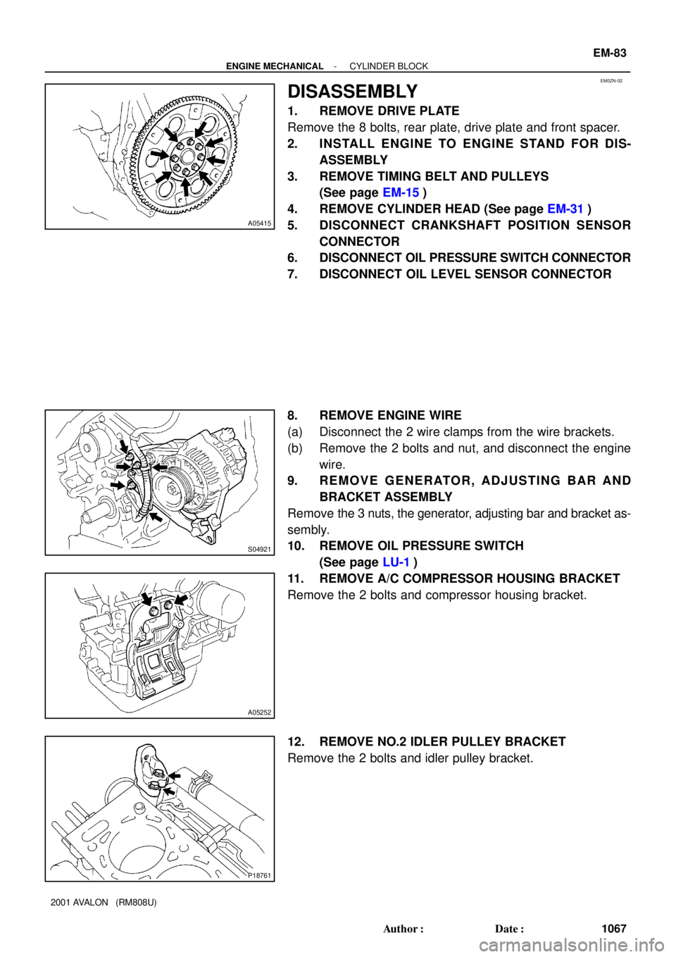
1. REMOVE DRIVE PLATE
Remove the 8 bolts, rear plate, drive plate and front spacer.
2. INSTALL ENGINE TO ENGINE STAND FOR DIS-
ASSEMBLY
3. REMOVE TIMING BELT AND PULLEYS
(See page EM-15)
4. REMOVE CYLINDER HEAD (See page EM-31)
5. DISCONNECT CRANKSHAFT POSITION SENSOR
CONNECTOR
6. DISCONNECT OIL PRESSURE SWITCH CONNECTOR
7. DISCONNECT OIL LEVEL SENSOR CONNECTOR
8. REMOVE ENGINE WIRE
(a) Disconnect the 2 wire clamps from the wire brackets.
(b) Remove the 2 bolts and nut, and disconnect the engine
wire.
9. REMOVE GENERATOR, ADJUSTING BAR AND
BRACKET ASSEMBLY
Remove the 3 nuts, the generator, adjusting bar and bracket as-
sembly.
10. REMOVE OIL PRESSURE SWITCH
(See page LU-1)
11. REMOVE A/C COMPRESSOR HOUSING BRACKET
Remove the 2 bolts and compressor housing bracket.
12. REMOVE NO.2 IDLER PULLEY BRACKET
Remove the 2 bolts and idler pulley bracket.
Page 1310 of 1897
A10530
A09696
Less than 6 mm
A10529
P12753
10 11
12 13
14
151
162
3
45
6
7
89
P25741
Painted Mark
Front90°
90° EM-104
- ENGINE MECHANICALCYLINDER BLOCK
1088 Author�: Date�:
2001 AVALON (RM808U)
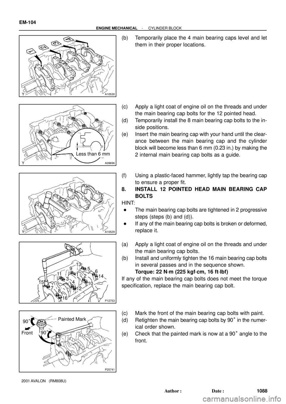
(b) Temporarily place the 4 main bearing caps level and let
them in their proper locations.
(c) Apply a light coat of engine oil on the threads and under
the main bearing cap bolts for the 12 pointed head.
(d) Temporarily install the 8 main bearing cap bolts to the in-
side positions.
(e) Insert the main bearing cap with your hand until the clear-
ance between the main bearing cap and the cylinder
block will become less than 6 mm (0.23 in.) by making the
2 internal main bearing cap bolts as a guide.
(f) Using a plastic-faced hammer, lightly tap the bearing cap
to ensure a proper fit.
8. INSTALL 12 POINTED HEAD MAIN BEARING CAP
BOLTS
HINT:
�The main bearing cap bolts are tightened in 2 progressive
steps (steps (b) and (d)).
�If any of the main bearing cap bolts is broken or deformed,
replace it.
(a) Apply a light coat of engine oil on the threads and under
the main bearing cap bolts.
(b) Install and uniformly tighten the 16 main bearing cap bolts
in several passes and in the sequence shown.
Torque: 22 N´m (225 kgf´cm, 16 ft´lbf)
If any of the main bearing cap bolts does not meet the torque
specification, replace the main bearing cap bolt.
(c) Mark the front of the main bearing cap bolts with paint.
(d) Retighten the main bearing cap bolts by 90° in the numer-
ical order shown.
(e) Check that the painted mark is now at a 90° angle to the
front.
Page 1315 of 1897
P00601
A05416
1
2 34 5
67
8
- ENGINE MECHANICALCYLINDER BLOCK
EM-109
1093 Author�: Date�:
2001 AVALON (RM808U)
30. INSTALL OIL PRESSURE SWITCH
(See page LU-1)
31. INSTALL GENERATOR, BRACKET AND ADJUSTING
BAR ASSEMBLY
Torque: 43 N´m (440 kgf´cm, 32 ft´lbf)
32. INSTALL ENGINE WIRE
33. CONNECT OIL LEVEL SENSOR CONNECTOR
34. CONNECT OIL PRESSURE SWITCH CONNECTOR
35. CONNECT CRANKSHAFT POSITION SWITCH CON-
NECTOR
36. INSTALL CYLINDER HEAD (See page EM-59)
37. INSTALL TIMING PULLEYS AND BELT
(See page EM-21)
38. REMOVE ENGINE STAND
39. INSTALL DRIVE PLATE
(a) Apply adhesive to 2 or 3 threads of the bolt end.
Adhesive: Part No. 08833-00070, THREE BOND 1324
or equivalent
(b) Install the front spacer, drive plate and rear plate on the
crankshaft.
(c) Install and uniformly tighten the 8 bolts in several passes
and in the sequence shown.
Torque: 83 N´m (850 kgf´cm, 61 ft´lbf)
Page 1337 of 1897
P12974
SST
Main Gear
Sub-Gear
A05201
90°Exhaust
P12804
Exhaust
Front
A02008
Exhaust
Seal
Packing
- ENGINE MECHANICALCYLINDER HEAD
EM-61
1045 Author�: Date�:
2001 AVALON (RM808U)
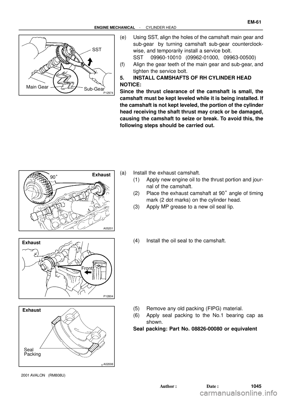
(e) Using SST, align the holes of the camshaft main gear and
sub-gear by turning camshaft sub-gear counterclock-
wise, and temporarily install a service bolt.
SST 09960-10010 (09962-01000, 09963-00500)
(f) Align the gear teeth of the main gear and sub-gear, and
tighten the service bolt.
5. INSTALL CAMSHAFTS OF RH CYLINDER HEAD
NOTICE:
Since the thrust clearance of the camshaft is small, the
camshaft must be kept leveled while it is being installed. If
the camshaft is not kept leveled, the portion of the cylinder
head receiving the shaft thrust may crack or be damaged,
causing the camshaft to seize or break. To avoid this, the
following steps should be carried out.
(a) Install the exhaust camshaft.
(1) Apply new engine oil to the thrust portion and jour-
nal of the camshaft.
(2) Place the exhaust camshaft at 90° angle of timing
mark (2 dot marks) on the cylinder head.
(3) Apply MP grease to a new oil seal lip.
(4) Install the oil seal to the camshaft.
(5) Remove any old packing (FIPG) material.
(6) Apply seal packing to the No.1 bearing cap as
shown.
Seal packing: Part No. 08826-00080 or equivalent
Page 1339 of 1897
A05195
Intake
Service Bolt
A05208
Exhaust
90°
P12805
Exhaust
Front
A02008
Exhaust
Seal
Packing
A05209
Exhaust
- ENGINE MECHANICALCYLINDER HEAD
EM-63
1047 Author�: Date�:
2001 AVALON (RM808U)
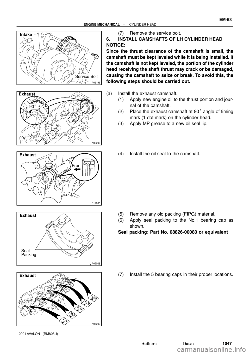
(7) Remove the service bolt.
6. INSTALL CAMSHAFTS OF LH CYLINDER HEAD
NOTICE:
Since the thrust clearance of the camshaft is small, the
camshaft must be kept leveled while it is being installed. If
the camshaft is not kept leveled, the portion of the cylinder
head receiving the shaft thrust may crack or be damaged,
causing the camshaft to seize or break. To avoid this, the
following steps should be carried out.
(a) Install the exhaust camshaft.
(1) Apply new engine oil to the thrust portion and jour-
nal of the camshaft.
(2) Place the exhaust camshaft at 90° angle of timing
mark (1 dot mark) on the cylinder head.
(3) Apply MP grease to a new oil seal lip.
(4) Install the oil seal to the camshaft.
(5) Remove any old packing (FIPG) material.
(6) Apply seal packing to the No.1 bearing cap as
shown.
Seal packing: Part No. 08826-00080 or equivalent
(7) Install the 5 bearing caps in their proper locations.
Page 1353 of 1897
A07281
Manifold
Stay
A07283
O-Ring
A05193
A05280Align Intake
- ENGINE MECHANICALCYLINDER HEAD
EM-35
1019 Author�: Date�:
2001 AVALON (RM808U)
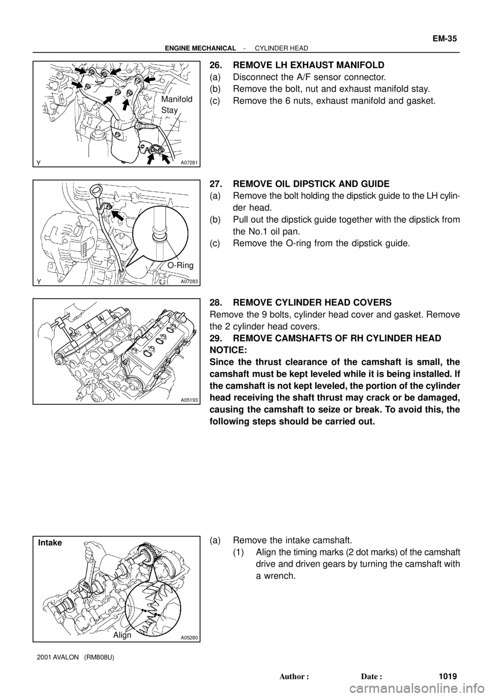
26. REMOVE LH EXHAUST MANIFOLD
(a) Disconnect the A/F sensor connector.
(b) Remove the bolt, nut and exhaust manifold stay.
(c) Remove the 6 nuts, exhaust manifold and gasket.
27. REMOVE OIL DIPSTICK AND GUIDE
(a) Remove the bolt holding the dipstick guide to the LH cylin-
der head.
(b) Pull out the dipstick guide together with the dipstick from
the No.1 oil pan.
(c) Remove the O-ring from the dipstick guide.
28. REMOVE CYLINDER HEAD COVERS
Remove the 9 bolts, cylinder head cover and gasket. Remove
the 2 cylinder head covers.
29. REMOVE CAMSHAFTS OF RH CYLINDER HEAD
NOTICE:
Since the thrust clearance of the camshaft is small, the
camshaft must be kept leveled while it is being installed. If
the camshaft is not kept leveled, the portion of the cylinder
head receiving the shaft thrust may crack or be damaged,
causing the camshaft to seize or break. To avoid this, the
following steps should be carried out.
(a) Remove the intake camshaft.
(1) Align the timing marks (2 dot marks) of the camshaft
drive and driven gears by turning the camshaft with
a wrench.
Page 1354 of 1897
A05195
IntakeMain Gear
Sub-Gear
Service Bolt
A05207
Intake
7
8
5
6
3
41 2
9
10
A05197
7
85
6
3
41
2
9
10 Exhaust EM-36
- ENGINE MECHANICALCYLINDER HEAD
1020 Author�: Date�:
2001 AVALON (RM808U)
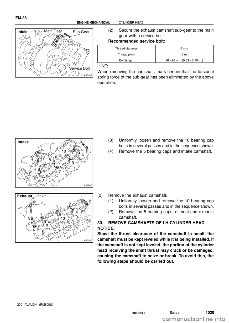
(2) Secure the exhaust camshaft sub-gear to the main
gear with a service bolt.
Recommended service bolt:
Thread diameter6 mm
Thread pitch1.0 mm
Bolt length16 - 20 mm (0.63 - 0.79 in.)
HINT:
When removing the camshaft, mark certain that the torsional
spring force of the sub-gear has been eliminated by the above
operation.
(3) Uniformly loosen and remove the 10 bearing cap
bolts in several passes and in the sequence shown.
(4) Remove the 5 bearing caps and intake camshaft.
(b) Remove the exhaust camshaft.
(1) Uniformly loosen and remove the 10 bearing cap
bolts in several passes and in the sequence shown.
(2) Remove the 5 bearing caps, oil seal and exhaust
camshaft.
30. REMOVE CAMSHAFTS OF LH CYLINDER HEAD
NOTICE:
Since the thrust clearance of the camshaft is small, the
camshaft must be kept leveled while it is being installed. If
the camshaft is not kept leveled, the portion of the cylinder
head receiving the shaft thrust may crack or be damaged,
causing the camshaft to seize or break. To avoid this, the
following steps should be carried out.