Page 598 of 1897
F09799
ABS Actuator and ECU
A7 20
WA
Engine Room J/BEngine Room R/B No. 5
AM1
5 512
BIgnition Switch Driver Side J/B Multi Display
GAUGE No. 1
IG1 Relay10
1D
12
3 44
1C 3
1B1
1G W J/B No. 4
ABS
M65
M64
13
4F4
4DIE115
Battery FL Block
ALT 1
F8F61
BFL MAIN
IGB
B 7 A21
Active Light Relay
1 R-L
R-L
B-L ABS
D2
DLC215 4B
J/B No. 4
15 4A15
4HR-L
R-B R-B
4
W-R
IG1 AM12
7
IF1
1
2G1
2H
1
F10 W-BW-L
W-L 14
- DIAGNOSTICSANTI-LOCK BRAKE SYSTEM WITH ELECTRONIC
BRAKE FORCE DISTRIBUTION (EBD)DI-243
399 Author�: Date�:
2001 AVALON (RM808U)
ABS Warning Light Circuit
CIRCUIT DESCRIPTION
If the ECU detects trouble, the ABS warning light lights up and ABS control is prohibited at the same time.
At this time, the ECU records a DTC in memory.
Connecting terminals Tc and E
1 of the DLC1 makes the ABS warning light blink and output the DTC.
WIRING DIAGRAM
DI6NM-02
Page 599 of 1897

400 Author�: Date�:
2001 AVALON (RM808U)
INSPECTION PROCEDURE
Troubleshooting in accordance with the chart")
DI-244- DIAGNOSTICSANTI-LOCK BRAKE SYSTEM WITH ELECTRONIC
BRAKE FORCE DISTRIBUTION (EBD)
400 Author�: Date�:
2001 AVALON (RM808U)
INSPECTION PROCEDURE
Troubleshooting in accordance with the chart below for each trouble symptom.
ABS warning light does not light upGo to step 1
ABS warning light remains onGo to step 2
1 Check ABS warning light.
See combination meter troubleshooting on page BE-2.
NG Repair bulb or combination meter assembly.
OK
2 Check active lamp relay.
NG Replace active lamp relay.
OK
Check for open circuit in harness and connector between GAUGE fuse and active lamp relay,
ECU-IG No. 2 fuse and active lamp relay, short circuit between active lamp relay and ABS ECU
(See page IN-30).
3 Is DTC output?
Check the DTC on page DI-212.
YES Repair circuit indicated by the code output.
NO
Check for short circuit in harness and connector and active lamp relay, ECU-IG No. 2 fuse and
active lamp relay, short circuit between active lamp relay and ABS ECU (See page IN-30).
Page 600 of 1897
DI-238- DIAGNOSTICSANTI-LOCK BRAKE SYSTEM WITH ELECTRONIC
BRAKE FORCE DISTRIBUTION (EBD)
394 Author�: Date�:
2001 AVALON (RM808U)
DTC Always ON ABS ECU Malfunction
CIRCUIT DESCRIPTION
DTC No.DTC Detecting ConditionTrouble Area
Always ON
Either of the following 1., 2. or 3. is detected:
1. The ECU connectors are OFF the ECU.
2. There is a malfunction in the ECU internal circuit.
3. There is a malfunction in ABS warning light circuit.
�Charging system
�ABS warning light circuit
INSPECTION PROCEDURE
1 Check that the ECU connectors are securely connected to the ECU.
NO Connect the connector to the ECU.
YES
2 Is DTC output?
Check DTC on page DI-212.
YES Repair circuit indicated by the output code.
NO
3 Does ABS warning light go off?
YES Check for open or short circuit in harness and
connector between ECU-IG fuse and ECU (See
page IN-30).
NO
DI6NK-01
Page 601 of 1897
- DIAGNOSTICSANTI-LOCK BRAKE SYSTEM WITH ELECTRONIC
BRAKE FORCE DISTRIBUTION (EBD)DI-239
395 Author�: Date�:
2001 AVALON (RM808U)
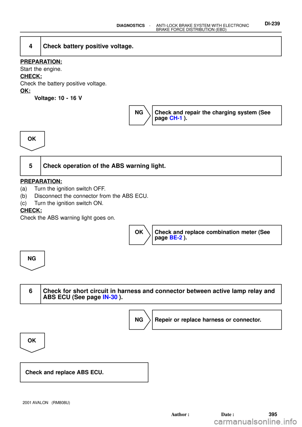
4 Check battery positive voltage.
PREPARATION:
Start the engine.
CHECK:
Check the battery positive voltage.
OK:
Voltage: 10 - 16 V
NG Check and repair the charging system (See
page CH-1).
OK
5 Check operation of the ABS warning light.
PREPARATION:
(a) Turn the ignition switch OFF.
(b) Disconnect the connector from the ABS ECU.
(c) Turn the ignition switch ON.
CHECK:
Check the ABS warning light goes on.
OK Check and replace combination meter (See
page BE-2).
NG
6 Check for short circuit in harness and connector between active lamp relay and
ABS ECU (See page IN-30).
NG Repeir or replace harness or connector.
OK
Check and replace ABS ECU.
Page 602 of 1897
F09801
ABS Actuator
and ECU
A713
Battery J/B No. 3A21
Active Light Relay
Multi DisplayY-B
BRAKEPKB
PKB
Ignition Switch
IF1 A721
EBDW IE15
Y-B
6 5
8 3 Y-G
3B14
3A
6 3B
5
Y-G
B4
15R-W
IE116
R-Y
Y-G
1
P3
Parking
Brake
Switch W-BBody ECU
J1
J/CDriver Side J/B
B1
Bake Fluid
Level Warning
Switch
J/B No. 3
R-W3H
153B
15
15
3A
12
1I8
1H
R-W
1
2
B B
Engine Room J/BDriver Side J/BGAUGE No. 1 IG1 Relay
4
2D4
2F
W-B
ED
R-WR-WIC17
M63
M64R-B
J/B No. 4
13
4F4
4D
R-B
10
1D 1
2
3 44
1C 3
1B1
1G W
IGW-BEngine Room J/BEngine Room R/B No. 57
BAM1
B-L
FL Block
ALT5 512 1
2H 1
2G
1
F8
F10F61
BFL MAIN W-B
142
W-R
W-L
W-L R-Y DI-240
- DIAGNOSTICSANTI-LOCK BRAKE SYSTEM WITH ELECTRONIC
BRAKE FORCE DISTRIBUTION (EBD)
396 Author�: Date�:
2001 AVALON (RM808U)
BRAKE Warning Light Circuit
CIRCUIT DESCRIPTION
The BRAKE warning light lights up when the brake fluid is insufficient, parking brake is applied or the EBD
is defective.
WIRING DIAGRAM
DI6NL-02
Page 603 of 1897
- DIAGNOSTICSANTI-LOCK BRAKE SYSTEM WITH ELECTRONIC
BRAKE FORCE DISTRIBUTION (EBD)DI-241
397 Author�: Date�:
2001 AVALON (RM808U)
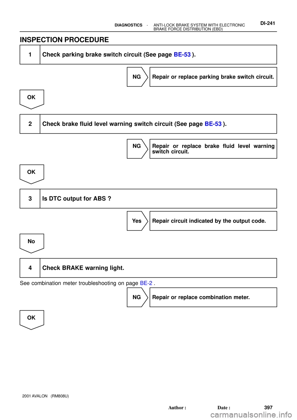
INSPECTION PROCEDURE
1 Check parking brake switch circuit (See page BE-53).
NG Repair or replace parking brake switch circuit.
OK
2 Check brake fluid level warning switch circuit (See page BE-53).
NG Repair or replace brake fluid level warning
switch circuit.
OK
3 Is DTC output for ABS ?
Yes Repair circuit indicated by the output code.
No
4 Check BRAKE warning light.
See combination meter troubleshooting on page BE-2.
NG Repair or replace combination meter.
OK
Page 621 of 1897
F09800
ABS Actuator
and ECU
A714
STP Driver Side J/B
BatteryJ/B No. 4
S4
Stop Light SwitchR7
Rear Combination
Light LH
G-W
14
IE1 G-W
G-W
J/B No. 3
16
4D 16
4F G-W3
3F 3
3C 5
1B 3
1D
4
1E
12R
11
1D STOP
FL Block
FL MAIN
L5
Light Failure
SensorStop
J12
J/C 1
1G W
1
F101
F6B5
IK1
7
Stop
36
G-R
B BBW-B
C
C
W-B
R8
Rear Combination
Light RH
36
G-R
G-R 2
1R-WH11
High Mounted
Stop Light
21
W-BC
C
W-B
BM ALTG-W G-W
G-W Driver Side J/B
J12
J/C DI-234
- DIAGNOSTICSANTI-LOCK BRAKE SYSTEM WITH ELECTRONIC
BRAKE FORCE DISTRIBUTION (EBD)
390 Author�: Date�:
2001 AVALON (RM808U)
DTC 58 Stop Light Switch Circuit
CIRCUIT DESCRIPTION
DTC No.DTC Detecting ConditionTrouble Area
58
Stop light switch circuit is open, and stop light switch volt-
age is in the level between 55 % and 75 % of the battery
voltage.�Stop light switch
�Stop light switch circuit
WIRING DIAGRAM
DI6NI-02
Page 622 of 1897
 (-)
14A7
- DIAGNOSTICSANTI-LOCK BRAKE SYSTEM WITH ELECTRONIC
BRAKE FORCE DISTRIBUTION (EBD)DI-235
391 Author�: Date�:
2001 AVALON (RM808U)
INSPECTION PROCEDURE
1 Check operation of stop")
F00069
(+) (-)
14A7
- DIAGNOSTICSANTI-LOCK BRAKE SYSTEM WITH ELECTRONIC
BRAKE FORCE DISTRIBUTION (EBD)DI-235
391 Author�: Date�:
2001 AVALON (RM808U)
INSPECTION PROCEDURE
1 Check operation of stop light.
CHECK:
Check that the stop light lights up when the brake pedal is depressed and turns off when the brake pedal
is released.
NG Repair stop light circuit (See page BE-36).
OK
2 Check voltage between terminal STP (A7 - 14) of brake actuator and body
ground.
PREPARATION:
Disconnect the connector from the brake actuator.
CHECK:
Measure the voltage between terminal A7 - 14 of brake actua-
tor harness side connector and body ground when the brake
pedal is depressed.
OK:
Voltage: 8 - 14 V
OK Check and replace ABS ECU.
NG
3 Check for open circuit in harness and connector between terminal STP of brake
actuator and stop light switch (See page IN-30).
NG Repair or replace harness or connector.
OK
Proceed to next circuit inspection shown in
problem symptoms table (See page
DI-218).