Page 466 of 1897
BO2PQ-01
N21523
H10166
N21424
H12170
- BODYSLIDING ROOF
BO-81
1866 Author�: Date�:
2001 AVALON (RM808U)
DISASSEMBLY
1. REMOVE SLIDING ROOF PANEL STOPPER
(a) Remove the screw and stopper.
(b) Employ the same manner described above to the other
side.
2. REMOVE SUNSHADE TRIM
3. REMOVE REAR ROOF DRIP CHANNEL
Remove the 2 screws and rear roof drip channel as shown in
the illustration.
4. REMOVE REAR FRAME
Remove the 4 screws and rear frame.
5. REMOVE DRIVE CABLE
(a) Remove the screws and guide rail stopper.
(b) Remove the screw from the sliding roof housing.
(c) Slightly lift the sliding roof housing, and slide the drive
cable rearward to then remove it.
HINT:
�At the time of reassembly, please refer to the following
items.
�Adjust the drive cable to a closed and tilted down position.
Page 472 of 1897
BO2PP-01
H12168
- BODYSLIDING ROOF
BO-79
1864 Author�: Date�:
2001 AVALON (RM808U)
REMOVAL
1. REMOVE ROOF HEADLINING (See page BO-99)
2. REMOVE SIDE GARNISH
(a) Using a screwdriver, remove the garnish.
HINT:
Tape the screwdriver tip before use.
(b) Employ the same manner described above to the other
side.
3. REMOVE SLIDING ROOF GLASS ASSEMBLY
(a) Using a torx wrench, remove the 4 nuts.
Torque: 4.0 N´m (41 kgf´cm, 35 in.´lbf)
(b) Pull the glass upward to remove it.
4. REMOVE DRIVE GEAR
NOTICE:
Remove the drive gear with the sliding roof fully closed.
(a) Disconnect the connector.
(b) Remove the 2 bolts an drive gear.
Torque: 5.4 N´m (55 kgf´cm, 48 in.´lbf)
(c) Remove the 2 screws and map light bracket from the drive
gear.
Page 480 of 1897

12. INSTALL WINDSHIELD GLASS AND MOULDING
(a) Install")
BO2821
H00679
H12153
w/o Rain gutter:
H12154
a
b
b - b a - aa
b w/ Rain gutter: BO-62
- BODYWINDSHIELD
1847 Author�: Date�:
2001 AVALON (RM808U)
12. INSTALL WINDSHIELD GLASS AND MOULDING
(a) Install the glass, aligning the reference marks using a suc-
tion rubber.
HINT:
Check to see that the stoppers are attached to the body correct-
ly.
(b) Lightly press the glass front surface for close contact.
(c) Correct insufficient or protruded adhesive agent using a
spatula.
HINT:
Apply adhesive agent up to the windshield glass edge.
(d) Install a new windshield moulding to the windshield glass
before the adhesive agent hardens.
HINT:
Install the moulding, aligning the center of moulding with the
center of body.
(e) Remove any excessive adhesive agent before it hardens.
(f) Hold the glass and moulding in place securely with a pro-
tective tape or equivalent until the adhesive hardens.
NOTICE:
Take care not to drive the vehicle during the time described
in the table below.
TemperatureMinimum time prior to driving the vehicle
35 °C (95 °F)1.5 hours
20 °C (68 °F)5 hours
5 °C (41 °F)24 hours
13. INSPECT FOR LEAK AND REPAIR
NOTICE:
Conduct a leak test after the hardening time has elapsed.
14. w/ Sliding roof:
INSTALL SLIDING ROOF OPENING TRIM
15. INSTALL ASSIST GRIP
16. INSTALL COWL TOP VENTILATOR LOUVER
17. INSTALL HOOD TO COWL TOP SEAL
18. INSTALL WIPER ARMS
(a) Operate the wiper motor once and turn the wiper switch
OFF.
(b) Install the wiper arms and tighten nuts by hand.
Page 482 of 1897

REMOVAL
1. REMOVE INNER REAR VIEW MIRROR
(a) w/ Electrochromic rear view mirror:
Using a")
BO2PF-01
H12143
H12144
H121452 Clips
H12129
BO-56
- BODYWINDSHIELD
1841 Author�: Date�:
2001 AVALON (RM808U)
REMOVAL
1. REMOVE INNER REAR VIEW MIRROR
(a) w/ Electrochromic rear view mirror:
Using a screwdriver, remove the inner rear view mirror
cover.
HINT:
Tape the screwdriver tip before use.
(b) w/ Electrochromic rear view mirror:
Disconnect the connector.
(c) Remove the inner rear view mirror as shown in the illustra-
tion.
2. REMOVE SUN VISORS AND HOLDERS
3. REMOVE ROOF CONSOLE BOX
(a) Using a screwdriver, remove the map light lens.
HINT:
Tape the screwdriver tip before use.
(b) Remove the 3 screws and roof console box, then discon-
nect the connector.
4. REMOVE FRONT DOOR OPENING TRIMS
5. REMOVE FRONT PILLAR GARNISH
(a) Remove the front pillar garnish.
(b) Employ the same manner described above to the other
side.
6. REMOVE WIPER ARMS
7. REMOVE HOOD TO COWL TOP SEAL
8. REMOVE COWL TOP VENTILATOR LOUVER
(a) Using a clip remover, remove the 2 clips.
(b) Remove the cowl top ventilator louver as shown in the il-
lustration.
9. REMOVE ASSIST GRIP
10. w/ Sliding roof:
REMOVE SLIDING ROOF OPENING TRIM
Page 495 of 1897

INSTALLATION
1. INSTALL BRAKE BOOSTER
(a) Install the booster")
BR152-01
F05420
SST Master
Cylinder
F05422
SST
F05421
SST
BR-24
- BRAKEBRAKE BOOSTER ASSEMBLY
1423 Author�: Date�:
2001 AVALON (RM808U)
INSTALLATION
1. INSTALL BRAKE BOOSTER
(a) Install the booster and a new gasket.
(b) Install the clevis to the operating rod.
(c) Install and torque the booster installation nuts.
Torque: 13 N´m (130 kgf´cm, 9 ft´lbf)
(d) Install the clevis pin into the clevis and brake pedal, and
install the clip to the clevis pin.
(e) Install the pedal return spring.
2. ADJUST LENGTH OF BOOSTER PUSH ROD
(a) Set the SST on the master cylinder, and lower the pin until
its tip slightly touches the piston.
SST 09737-0001 1
(b) Turn the SST upside down, and set it on the booster.
SST 09737-0001 1
(c) Measure the clearance between the booster push rod
and pin head (SST).
Clearance: 0 mm (0 in.)
(d) Using SST, adjust the booster push rod length until the
push rod lightly touches the pin head.
SST 09737-00020
3. w/ VSC:
INSTALL PRECHARGE PUMP ASSEMBLY (See page
BR-58)
4. INSTALL MASTER CYLINDER (See page BR-20)
5. CONNECT VACUUM HOSE TO BRAKE BOOSTER
6. FILL BRAKE RESERVOIR WITH BRAKE FLUID AND
BLEED BRAKE SYSTEM (See page BR-4)
7. CHECK FOR LEAKS
8. CHECK AND ADJUST BRAKE PEDAL (See page
BR-6)
9. INSTALL NO. 2 HEATER TO REGISTER DUCT, LOWER
LH INSTRUMENT PANEL INSERT AND LOWER NO. 1
INSTRUMENT PANEL (See page BO-87)
10. DO OPERATIONAL CHECK (See page BR-21)
Page 496 of 1897
BR2237
BR0KW-04
BR2238
GOODNO GOOD
2nd3rd
1st
- BRAKEBRAKE BOOSTER ASSEMBLY
BR-21
1420 Author�: Date�:
2001 AVALON (RM808U)
BRAKE BOOSTER ASSEMBLY
ON-VEHICLE INSPECTION
1. OPERATING CHECK
(a) Depress the brake pedal several times with the engine off
and check that there is no change in the pedal reserve
distance.
(b) Depress the brake pedal and start the engine. If the pedal
goes down slightly, operation is normal.
2. AIR TIGHTNESS CHECK
(a) Start the engine and stop it after 1 or 2 minutes. Depress
the brake pedal several times slowly.
If the pedal goes down farthest the 1st time, but gradually rises
after the 2nd or 3rd time, the booster is air tight.
(b) Depress the brake pedal while the engine is running, and
stop the engine with the pedal depressed.
If there is no change in the pedal reverse travel after holding the
pedal for 30 seconds, the booster is air tight.
Page 500 of 1897

DISASSEMBLY
1. REMOVE RESERVOIR
(a) Remove the set screw and pull out")
BR0KS-03
F09715
Soft Jows
F09716
Soft Jows
R12236
A BR-16
- BRAKEBRAKE MASTER CYLINDER
1415 Author�: Date�:
2001 AVALON (RM808U)
DISASSEMBLY
1. REMOVE RESERVOIR
(a) Remove the set screw and pull out the reservoir.
Torque: 1.7 N´m (17.5 kgf´cm, 15.2 in.´lbf)
(b) Remove the cap and strainer from the reservoir.
2. REMOVE 2 GROMMETS
3. w/o VSC:
PLACE CYLINDER IN VISE
4. w/o VSC:
REMOVE PISTON STOPPER BOLT
Using a screwdriver, push the pistons in all the way and remove
the piston stopper bolt and gasket.
HINT:
Tape the screwdriver tip before use.
Torque: 10 N´m (100 kgf´cm, 7 ft´lbf)
5. w/o VSC:
REMOVE 2 PISTONS AND SPRINGS
(a) Push in the piston with a screwdriver and remove the
snap ring with snap ring pliers.
HINT:
Tape the screwdriver tip before use.
(b) Remove the No. 1 piston and spring by hand, pulling
straight out, not at an angle.
NOTICE:
�If pulled out and install at an angle, there is a possibil-
ity that the cylinder bore could be damaged.
�At the time of reassembly, be careful not to damage
the rubber lips on the pistons.
(c) Place a rag and 2 wooden blocks on the work table, and
lightly tap the cylinder flange against the block edges until
the No. 2 piston drops out of the cylinder.
HINT:
Make sure that the distance (A) from the rag to the top of the
blocks is at least 100 mm (3.94 in.).
Page 508 of 1897
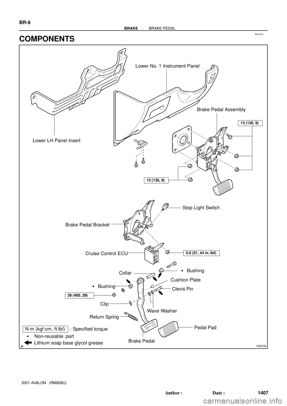
BR150-01
F09720
Brake Pedal Bracket Lower LH Panel Insert
Lower No. 1 Instrument Panel
Stop Light Switch
Cruise Control ECU
Pedal Pad
Clip
Return Spring
Collar
Wave Washer
Clevis Pin
Cushion Plate
� Bushing
� Bushing
Brake Pedal
Lithium soap base glycol grease
Non-reusable part �
Brake Pedal Assembly
N´m (kgf´cm, ft´lbf) : Specified torque
13 (130, 9)
39 (400, 29)
13 (130, 9)
5.0 (51, 44 in.´lbf)
BR-8
- BRAKEBRAKE PEDAL
1407 Author�: Date�:
2001 AVALON (RM808U)
COMPONENTS