Page 1778 of 1897

or less
- STEERINGPOWER STEERING FLUID
SR-5
1468 Author�: Date�:
2001 AVALON (RM808U)
INSPECTION
1.")
R11740
HOT
COLD
SR0EF-04
R11741
Normal Abnormal
R11786Engine Idling
Engine Stopped 5 mm (0.20 in.)
or less
- STEERINGPOWER STEERING FLUID
SR-5
1468 Author�: Date�:
2001 AVALON (RM808U)
INSPECTION
1. CHECK FLUID LEVEL
(a) Keep the vehicle level.
(b) With the engine stopped, check the fluid level in the oil
reservoir.
If necessary, add fluid.
Fluid: ATF DEXRON® II or III
HINT:
Check that the fluid level is within the HOT LEVEL range on the
reservoir. If the fluid is cold, check that it is within the COLD
LEVEL range.
(c) Start the engine and run it at idle.
(d) Turn the steering wheel from lock to lock several times to
boost fluid temperature.
Fluid temperature: 80°C (176°F)
(e) Check for foaming or emulsification.
If there is foaming or emulsification, bleed power steering sys-
tem (See page SR-4).
(f) With the engine idling, measure the fluid level in the oil
reservoir.
(g) Stop the engine.
(h) Wait a few minutes and remeasure the fluid level in the oil
reservoir.
Maximum fluid level rise: 5 mm (0.20 in.)
If a problem is found, bleed power steering system (See page
SR-4).
(i) Check the fluid level.
Page 1779 of 1897
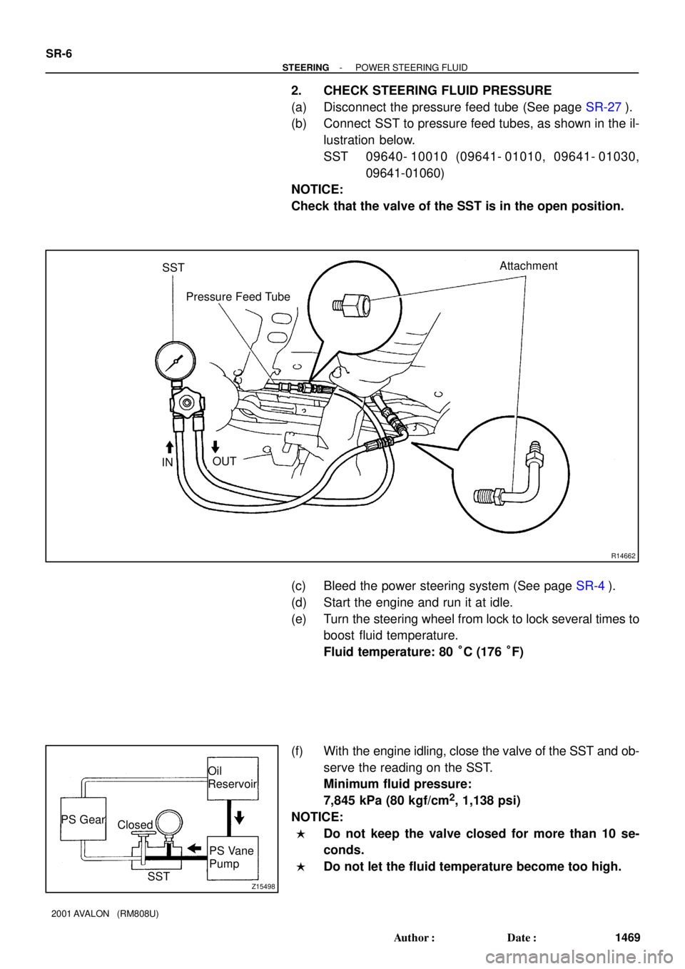
R14662
Attachment
IN
OUT Pressure Feed Tube SST
Z15498
Oil
Reservoir
PS Vane
Pump PS Gear
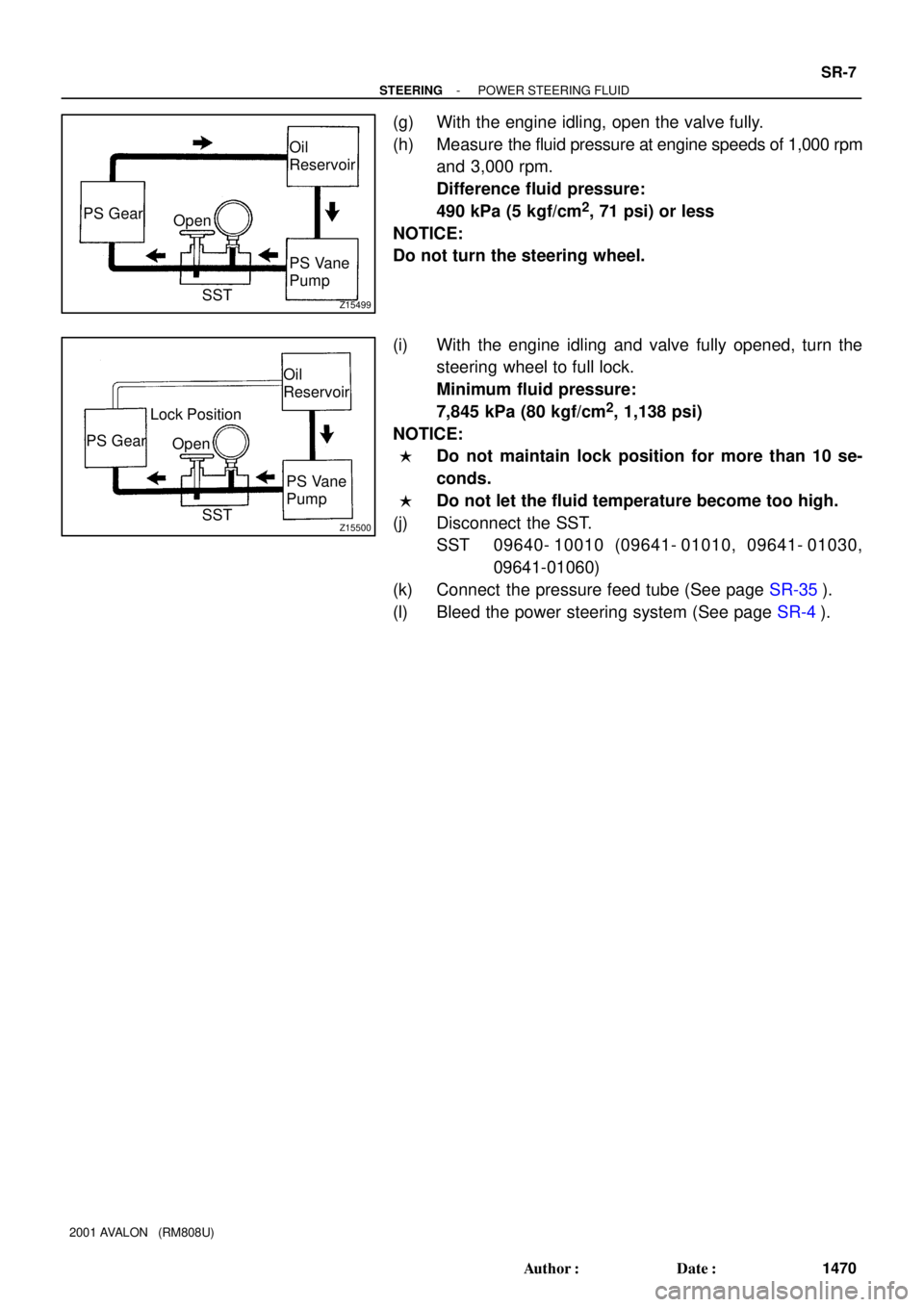
SST Closed SR-6
- STEERINGPOWER STEERING FLUID
1469 Author�: Date�:
2001 AVALON (RM808U)
2. CHECK STEERING FLUID PRESSURE
(a) Disconnect the pressure feed tube (See page SR-27).
(b) Connect SST to pressure feed tubes, as shown in the il-
lustration below.
SST 09640- 10010 (09641- 01010, 09641- 01030,
09641-01060)
NOTICE:
Check that the valve of the SST is in the open position.
(c) Bleed the power steering system (See page SR-4).
(d) Start the engine and run it at idle.
(e) Turn the steering wheel from lock to lock several times to
boost fluid temperature.
Fluid temperature: 80 °C (176 °F)
(f) With the engine idling, close the valve of the SST and ob-
serve the reading on the SST.
Minimum fluid pressure:
7,845 kPa (80 kgf/cm
2, 1,138 psi)
NOTICE:
�Do not keep the valve closed for more than 10 se-
conds.
�Do not let the fluid temperature become too high.
Page 1780 of 1897
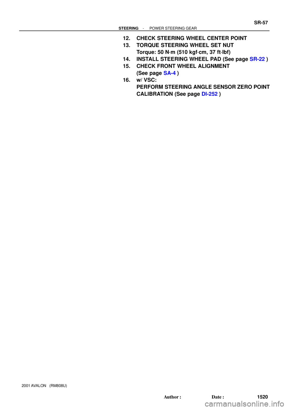
Z15499
Oil
Reservoir
PS Vane
Pump PS Gear
SST Open
Z15500
Oil
Reservoir
PS Vane
Pump PS Gear
SST Open Lock Position
- STEERINGPOWER STEERING FLUID
SR-7
1470 Author�: Date�:
2001 AVALON (RM808U)
(g) With the engine idling, open the valve fully.
(h) Measure the fluid pressure at engine speeds of 1,000 rpm
and 3,000 rpm.
Difference fluid pressure:
490 kPa (5 kgf/cm
2, 71 psi) or less
NOTICE:
Do not turn the steering wheel.
(i) With the engine idling and valve fully opened, turn the
steering wheel to full lock.
Minimum fluid pressure:
7,845 kPa (80 kgf/cm
2, 1,138 psi)
NOTICE:
�Do not maintain lock position for more than 10 se-
conds.
�Do not let the fluid temperature become too high.
(j) Disconnect the SST.
SST 09640- 10010 (09641- 01010, 09641- 01030,
09641-01060)
(k) Connect the pressure feed tube (See page SR-35).
(l) Bleed the power steering system (See page SR-4).
Page 1789 of 1897

INSTALLATION
1. INSTALL PS GEAR ASSEMBLY
(a) Install the PS gear assembly from the LH")
SR0EY-06
F13589
SST
Fulcrum Length
SR-56
- STEERINGPOWER STEERING GEAR
1519 Author�: Date�:
2001 AVALON (RM808U)
INSTALLATION
1. INSTALL PS GEAR ASSEMBLY
(a) Install the PS gear assembly from the LH of the vehicle.
NOTICE:
Do not damage the turn pressure tubes.
(b) Install the 2 gear assembly set bolts and nuts.
Torque: 181 N´m (1,850 kgf´cm, 134 ft´lbf)
HINT:
Lift up the stabilizer bar and install the bolts.
2. INSTALL NO. 1 FUEL TUBE PROTECTOR
Install the No. 1 fuel tube protector with 2 bolts and nut.
3. CONNECT STABILIZER BAR
Connect the stabilizer bar with the 4 bolts.
Torque: 19 N´m (190 kgf´cm, 14 ft´lbf)
4. CONNECT PRESSURE FEED AND RETURN TUBES
(a) Coat 2 new O-rings with power steering fluid and install
them to the pressure feed and return tubes.
(b) Using SST, connect the pressure feed and return tubes.
SST 09023-38400
Torque: 28 N´m (290 kgf´cm, 21 ft´lbf)
HINT:
�Use a torque wrench with a fulcrum length of 300 mm
(11.81 in.).
�This torque value is effective in case that SST is parallel
to a torque wrench.
5. CONNECT CLAMP PLATE
Connect the clamp plate with nut.
Torque: 10 N´m (100 kgf´cm, 7 ft´lbf)
6. CONNECT INTERMEDIATE SHAFT SUB-ASSEMBLY
(See page SR-22)
7. CONNECT RH AND LH TIE ROD ENDS
(See page SA-13)
8. PLACE FRONT WHEELS FACING STRAIGHT AHEAD
HINT:
Do it with the front of the vehicle jacked up.
9. CENTER SPIRAL CABLE (See page SR-22)
10. INSTALL STEERING WHEEL
(a) Align the matchmarks on the steering wheel and steering
column main shaft.
(b) Temporarily tighten the steering wheel set nut.
(c) Connect the connector.
11. BLEED POWER STEERING SYSTEM
(See page SR-4)
Page 1790 of 1897
- STEERINGPOWER STEERING GEAR
SR-57
1520 Author�: Date�:
2001 AVALON (RM808U)
12. CHECK STEERING WHEEL CENTER POINT
13. TORQUE STEERING WHEEL SET NUT
Torque: 50 N´m (510 kgf´cm, 37 ft´lbf)
14. INSTALL STEERING WHEEL PAD (See page SR-22)
15. CHECK FRONT WHEEL ALIGNMENT
(See page SA-4)
16. w/ VSC:
PERFORM STEERING ANGLE SENSOR ZERO POINT
CALIBRATION (See page DI-252)
Page 1796 of 1897

or less
SST
R00429
Matchmarks SR-54
- STEERINGPOWER STEERING GEAR
1517 Author�: Date�:
2001 AVALON (RM808U)
(c) Using a brass bar and hammer, stake the")
R11668
Brass Bar
R11669
W04223
2 mm
(0.79 in.)
or less
SST
R00429
Matchmarks SR-54
- STEERINGPOWER STEERING GEAR
1517 Author�: Date�:
2001 AVALON (RM808U)
(c) Using a brass bar and hammer, stake the claw washer.
NOTICE:
Avoid any impact on the steering rack.
(d) Employ the same manner described above to the other
side.
18. INSTALL RH AND LH RACK BOOTS, CLAMPS AND
CLIPS
(a) Ensure that the steering rack hole is not clogged with
grease.
HINT:
If the hole is clogged, the pressure inside the rack boot will
change after it is assembled and the steering wheel is turned.
(b) Install the rack boot, clip and a new clamp.
NOTICE:
Be careful not to damage or twist the rack boot.
(c) Using SST, tighten the clamp as shown in the illustration.
SST 09521-24010
(d) Employ the same manner described above to the other
side.
19. INSTALL RH AND LH TIE ROD ENDS AND LOCK NUTS
(a) Screw the lock nut and tie rod end onto the rack end until
the matchmarks are aligned.
(b) After adjusting toe-in, torque the lock nut (See page
SA-4).
Torque: 74 N´m (750 kgf´cm, 54 ft´lbf)
(c) Employ the same manner described above to the other
side.
Page 1798 of 1897

REMOVAL
NOTICE:
Remove the steering wheel assembly before the steering
gear removal, because there i")
SR0EU-05
F13586
SST
SR-40
- STEERINGPOWER STEERING GEAR
1503 Author�: Date�:
2001 AVALON (RM808U)
REMOVAL
NOTICE:
Remove the steering wheel assembly before the steering
gear removal, because there is possibility of breaking of
the spiral cable.
1. PLACE FRONT WHEELS FACING STRAIGHT AHEAD
2. REMOVE STEERING WHEEL PAD (See page SR-12)
3. REMOVE STEERING WHEEL (See page SR-12)
4. DISCONNECT RH AND LH TIE ROD ENDS (See page
SA-9)
5. DISCONNECT INTERMEDIATE SHAFT SUB- AS-
SEMBLY (See page SR-12)
6. DISCONNECT CLAMP PLATE
Remove the nut and clamp plate.
7. DISCONNECT PRESSURE FEED AND RETURN
TUBES
(a) Using SST, disconnect the pressure feed and return
tubes.
SST 09023-38400
(b) Remove the 2 O-rings from the pressure feed and return
tubes.
8. DISCONNECT STABILIZER BAR
Remove the 4 bolts and disconnect the stabilizer bar.
HINT:
Do not remove the stabilizer bar.
9. REMOVE NO. 1 FUEL TUBE PROTECTOR
Remove the 2 bolts, nut and No. 1 fuel tube protector.
10. REMOVE PS GEAR ASSEMBLY
(a) Remove the 2 PS gear assembly set bolts and nuts.
HINT:
Lift up the stabilizer bar and remove the bolts.
(b) Remove the PS gear assembly from the LH of the vehicle.
NOTICE:
Do not damage the turn pressure tubes.
Page 1815 of 1897
F08857
SR0EG-05
F08858
SR-8
- STEERINGSTEERING WHEEL
1471 Author�: Date�:
2001 AVALON (RM808U)
STEERING WHEEL
INSPECTION
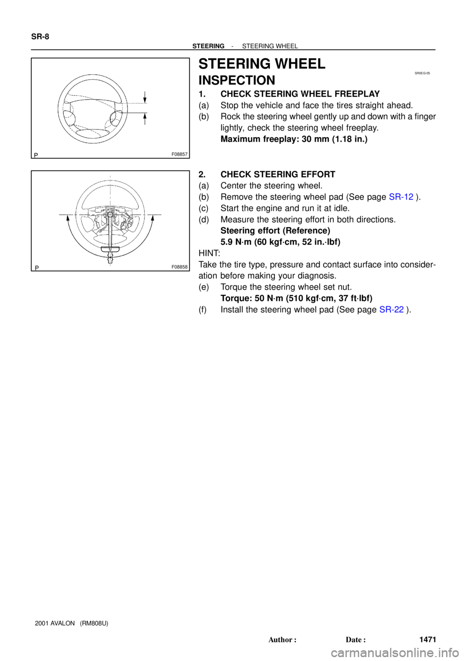
1. CHECK STEERING WHEEL FREEPLAY
(a) Stop the vehicle and face the tires straight ahead.
(b) Rock the steering wheel gently up and down with a finger
lightly, check the steering wheel freeplay.
Maximum freeplay: 30 mm (1.18 in.)
2. CHECK STEERING EFFORT
(a) Center the steering wheel.
(b) Remove the steering wheel pad (See page SR-12).
(c) Start the engine and run it at idle.
(d) Measure the steering effort in both directions.
Steering effort (Reference)
5.9 N´m (60 kgf´cm, 52 in.´lbf)
HINT:
Take the tire type, pressure and contact surface into consider-
ation before making your diagnosis.
(e) Torque the steering wheel set nut.
Torque: 50 N´m (510 kgf´cm, 37 ft´lbf)
(f) Install the steering wheel pad (See page SR-22).