Page 1843 of 1897
SA0W1-03
SA-24
- SUSPENSION AND AXLEFRONT DRIVE SHAFT
1358 Author�: Date�:
2001 AVALON (RM808U)
INSTALLATION
Installation is in the reverse order of removal (See page SA-16).
HINT:
After installation, check the ABS speed sensor signal (See page DI-212 or DI-252) and front wheel align-
ment (See page SA-4).
NOTICE:
w/ VSC:
After installation, perform the steering angle sensor zero point calibration (See page DI-252).
Page 1847 of 1897

REMOVAL
NOTICE:
�The hub bearing could be damaged if it is subjected
t")
SA0VY-02
FA1535
SST
W03093
W03142
F07389
SA-16
- SUSPENSION AND AXLEFRONT DRIVE SHAFT
1350 Author�: Date�:
2001 AVALON (RM808U)
REMOVAL
NOTICE:
�The hub bearing could be damaged if it is subjected
to the vehicle weight, such as when moving the ve-
hicle with the drive shaft removed.
Therefore, if it is absolutely necessary to place the ve-
hicle weight on the hub bearing, first support it with
SST.
SST 09608-16042 (09608-02021, 09608-02041)
�After disconnecting the drive shaft from the axle hub,
work carefully so as not to damage the ABS speed
sensor rotor serration on the drive shaft.
1. REMOVE FRONT WHEEL
Torque: 103 N´m (1,050 kgf´cm, 76 ft´lbf)
2. REMOVE FRONT FENDER APRON SEAL
3. DRAIN ATF
4. REMOVE DRIVE SHAFT LOCK NUT
(a) Remove the cotter pin and lock cap.
(b) While applying brakes, remove the nut.
Torque: 294 N´m (3,000 kgf´cm, 217 ft´lbf)
5. DISCONNECT TIE ROD END FROM STEERING
KNUCKLE (See page SA-9)
6. DISCONNECT LOWER SUSPENSION ARM FROM
LOWER BALL JOINT (See page SA-9)
7. DISCONNECT DRIVE SHAFT FROM AXLE HUB
Using a plastic hammer, disconnect the drive shaft from the axle
hub.
NOTICE:
Be careful not to damage the boot and ABS speed sensor
rotor.
8. LH drive shaft:
REMOVE DRIVE SHAFT
(a) Using a hub nut wrench and hammer handle or an equiva-
lent, remove the drive shaft.
NOTICE:
Be careful not to damage the dust cover and oil seal.
Page 1851 of 1897
SA0VD-03
R08850
R08861SSTSST
- SUSPENSION AND AXLEFRONT LOWER BALL JOINT
SA-39
1373 Author�: Date�:
2001 AVALON (RM808U)
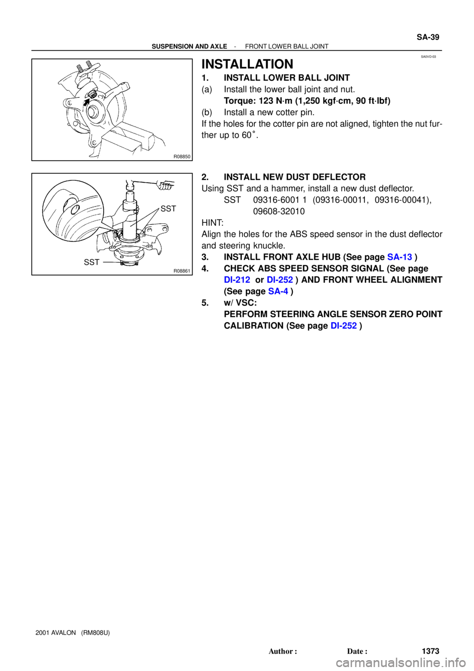
INSTALLATION
1. INSTALL LOWER BALL JOINT
(a) Install the lower ball joint and nut.
Torque: 123 N´m (1,250 kgf´cm, 90 ft´lbf)
(b) Install a new cotter pin.
If the holes for the cotter pin are not aligned, tighten the nut fur-
ther up to 60°.
2. INSTALL NEW DUST DEFLECTOR
Using SST and a hammer, install a new dust deflector.
SST 09316-6001 1 (09316-00011, 09316-00041),
09608-32010
HINT:
Align the holes for the ABS speed sensor in the dust deflector
and steering knuckle.
3. INSTALL FRONT AXLE HUB (See page SA-13)
4. CHECK ABS SPEED SENSOR SIGNAL (See page
DI-212 or DI-252) AND FRONT WHEEL ALIGNMENT
(See page SA-4)
5. w/ VSC:
PERFORM STEERING ANGLE SENSOR ZERO POINT
CALIBRATION (See page DI-252)
Page 1861 of 1897
SA0V5-03
- SUSPENSION AND AXLEFRONT SHOCK ABSORBER
SA-31
1365 Author�: Date�:
2001 AVALON (RM808U)
INSTALLATION
Installation is in the reverse order of removal (See page SA-26).
HINT:
After installation, check the front wheel alignment (See page SA-4).
NOTICE:
w/ VSC:
After installation, perform the steering angle sensor zero point calibration (See page DI-252).
Page 1863 of 1897

REMOVAL
1. REMOVE FRONT WHEEL
Torque: 103 N´m (1,050 kgf´cm, 76 ft´lbf)
2. DIS")
SA0V0-02
F07388
To outside SA-26
- SUSPENSION AND AXLEFRONT SHOCK ABSORBER
1360 Author�: Date�:
2001 AVALON (RM808U)
REMOVAL
1. REMOVE FRONT WHEEL
Torque: 103 N´m (1,050 kgf´cm, 76 ft´lbf)
2. DISCONNECT FLEXIBLE HOSE AND ABS SPEED
SENSOR WIRE HARNESS CLAMP
Remove the bolt and disconnect the flexible hose and ABS
speed sensor wire harness clamp from the shock absorber.
Torque: 29 N´m (300 kgf´cm, 22 ft´lbf)
3. DISCONNECT STABILIZER BAR LINK FROM SHOCK
ABSORBER (See page SA-41)
4. DISCONNECT SHOCK ABSORBER FROM STEERING
KNUCKLE
(a) Remove the 2 nuts and bolts on the lower side of the
shock absorber.
Torque: 211 N´m (2,150 kgf´cm, 156 ft´lbf)
(b) Remove the shock absorber from the steering knuckle.
HINT:
At the time of installation, coat the nut's threads with engine oil.
5. REMOVE SHOCK ABSORBER WITH COIL SPRING
Remove the 3 nuts and shock absorber with the coil spring.
Torque: 80 N´m (820 kgf´cm, 59 ft´lbf)
HINT:
At the time of installation, rotate the suspension support and set
it in the direction, as shown.
Page 1868 of 1897

FRONT WHEEL ALIGNMENT
INSPECTION
NOTICE:
w/ VSC:
Be")
F02090
Front:
Rear:SA1DP-04
Z03382
Alignment
TesterGauge SA-4
- SUSPENSION AND AXLEFRONT WHEEL ALIGNMENT
1338 Author�: Date�:
2001 AVALON (RM808U)
FRONT WHEEL ALIGNMENT
INSPECTION
NOTICE:
w/ VSC:
Be sure to perform the steering angle sensor zero point cal-
ibration after adjusting the front wheel alignment (See page
DI-252).
1. MEASURE VEHICLE HEIGHT
Vehicle height:
Front*1 mm (in.)Rear*2 mm (in.)
213 (8.39)266 (10.47)
*1: Front measuring point
Measure the distance from the ground to the center of the front
side lower suspension arm mounting bolt.
*
2: Rear measuring point
Measure the distance from the ground to the center of the front
side strut rod mounting bolt.
NOTICE:
Before inspecting the wheel alignment, adjust the vehicle
height to the specified value.
If the vehicle height is not the specified value, try to adjust it by
pushing down on or lifting the body.
2. INSTALL CAMBER-CASTER-KINGPIN GAUGE OR
POSITION VEHICLE ON WHEEL ALIGNMENT TES-
TER
Follow the specific instructions of the equipment manufacturer.
3. INSPECT CAMBER, CASTER AND STEERING AXIS
INCLINATION
Camber, caster and steering axis inclination:
Camber
Right-left error-0°37' ± 45' (-0.62° ± 0.75°)
45' (0.75°) or less
Caster
Right-left error2°10' ± 45' (2.17° ± 0.75°)
45' (0.75°) or less
Steering axis inclination
Right-left error13°04' ± 45' (13.07° ± 0.75°)
45' (0.75°) or less
If the caster and steering axis inclination are not within the spe-
cified values, after the camber has been correctly adjusted, re-
check the suspension parts for damaged and/or worn out parts.
Page 1870 of 1897

5. INSPECT TOE-IN
Toe-in:
Toe-in")
SA3213
Front A
DB
C
F02245
F02246
SA0028
Front AB
A B
A: Inside
B: Outside SA-6
- SUSPENSION AND AXLEFRONT WHEEL ALIGNMENT
1340 Author�: Date�:
2001 AVALON (RM808U)
5. INSPECT TOE-IN
Toe-in:
Toe-in
(total)A + B: 0° ± 12' (0° ± 0.2°)
C - D: 0 ± 2 mm (0 ± 0.08 in.)
If the toe-in is not within the specified value, adjust it at the rack
ends.
6. ADJUST TOE-IN
(a) Remove the rack boot set clips.
(b) Loosen the tie rod end lock nuts.
(c) Turn the right and left rack ends by an equal amount to
adjust the toe-in.
HINT:
Try to adjust the toe-in to the center of the specified value.
(d) Make sure that the lengths of the right and left rack ends
are the same.
Rack end length difference: 1.5 mm (0.059 in.) or less
(e) Torque the tie rod end lock nuts.
Torque: 74 N´m (750 kgf´cm, 54 ft´lbf)
(f) Place the boots on the seats and install the clips.
HINT:
Make sure that the boots are not twisted.
7. INSPECT WHEEL ANGLE
Turn the steering wheel fully, and measure the turning angle.
Wheel turning angle:
Inside wheel35°45' ± 1° (35.75° ± 1°)
Outside wheel: Reference31°23' (31.38°)
If the right and left inside wheel angles differ from the specified
value, check the right and left rack end lengths.
Page 1896 of 1897
W03084
- SUSPENSION AND AXLETIRE AND WHEEL
SA-3
1337 Author�: Date�:
2001 AVALON (RM808U)
4. CHECK WHEEL BEARING LOOSENESS
(a) Check the backlash in the bearing shaft direction.
Maximum: 0.05 mm (0.0020 in.)
(b) Check the axle hub deviation.
Maximum: 0.05 mm (0.0020 in.)
5. CHECK FRONT SUSPENSION FOR LOOSENESS
6. CHECK STEERING LINKAGE FOR LOOSENESS
7. CHECK BALL JOINT FOR LOOSENESS
8. CHECK SHOCK ABSORBER WORKS PROPERLY
�Check that oil leaks
�Check mounting bushings for wear
�Bounce front and rear of the vehicle